The creation of this article was prompted by my experience in creating power supplies and chargers based on simple switching power supplies, which are both SMPS on IR2153 and a converted different ways for power supply electronic transformer. These power supplies are simple, unstabilized switching power supplies without any protection. Despite these disadvantages, such power supplies are quite simple to manufacture, do not require complex configuration, and the time required to create such a power supply is less than for a full PWM power supply with stabilization and protection units.
By combining such a power supply and a simple PWM regulator on the NE555, we get an adjustable power supply both for experiments and for charging the battery. There is no limit to our joy until we try this device for a spark, or mistakenly, while thinking about creating the next device, mix up the polarity of the battery being charged. Shouting out with a loud bang and spraying acrid smoke into the room in which this embarrassment took place, the invention tells us that simple pulse block power supply, which is assembled according to a simplified introductory diagram cannot be reliable.
Then the idea came to find not just to introduce this or that protection unit into a specific instance of the power supply, but to find or create a universal high-speed circuit that can be implemented in any secondary power source.
Requirements for the protection unit:
Minimum details
The protection board should take up little space
Operable at high load currents
No relay
High response speed
One of the options that interested me was this diagram, found on the Internet:
When the output of this circuit is closed, the gate capacitance VT1 is discharged through the diode VD1, which leads to the closure of VT1 and no current flows through the transistor, the power supply remains safe and sound. But what happens if you connect a 300W load to the output of this circuit, when our power supply can only output 200W? Despite the fact that we have a protection circuit, the tortured power supply explodes again.
Disadvantages of this scheme:
1. It is necessary to accurately select the shunt resistance so that the maximum permissible current of the power supply creates such a voltage drop on the selected shunt that VT2, when opening, completely closes VT1.
2. In this circuit, there may come a time when the current passing through the shunt slightly opens VT2, as a result of which VT1 begins to close and remains in such a state that it will not be closed, and given that a considerable current flows through VT1, this linear mode will cause it to overheat severely , as a result of which VT1 will be broken.
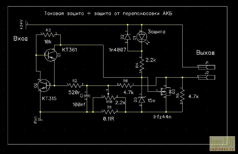
I once used trigger protection in a power supply on IR2153, and was pleased with its performance. Let's attach a shunt to the trigger latch circuit on a complementary pair of transistors as a current sensor and an n-channel transistor as key element we get the following diagram:
After power is applied to the circuit, transistor Q3, through the LED and R4, opens, the zener diode D3 limits the voltage at the gate of the field-effect transistor. D4 protects Q3 from emissions high voltage, when connecting an inductive load (electric motor). An analogue of a thyristor is assembled on a pair of transistors Q1, Q2. The current flowing through the shunt R1 causes a voltage drop, which from the motor of the variable resistor R10, and the circuit R2, C2, goes to the base of the transistor Q2. The amount of voltage from the shunt, which is proportional to the current flowing through this shunt, can be adjusted with a variable resistor R10. At the moment when the voltage at the base of Q2 becomes greater than 0.5-0.7V, transistor Q2 will begin to open, thereby opening Q1, in turn, transistor Q1, opening, will open Q2. This process happens very quickly, in a split second the transistors will open each other and remain in such a stable state. Through the open analogue of the thyristor, gate Q3, as well as resistor R4, will be connected to the common conductor of the circuit, which will lead to the closing of Q3 and the lighting of LED D1 will indicate that the protection has tripped. You can remove the protection either by briefly turning off the power or by briefly pressing the S1 button.
A universal protection circuit was created and tested in operation; shunt R1 was made up of two 0.22 Ohm 5W resistors. Remained last step- we introduce protection against polarity reversal of the battery terminals into the new circuit.
Circuit with reverse polarity protection:
Our circuit was supplemented with diode D2 and resistors R6, R5. Button S1 was removed from the circuit due to the fact that when the protection was triggered, it did not remove the circuit from protection after modification.
Current protection remains unchanged; the protection can be removed by turning off the power for 2-3 seconds. When connected to the output of the battery circuit, reversing the polarity, the voltage from the battery through diode D2, resistor R6 goes to the base of Q2, protection Q3 is triggered, the LED D1 signals that the protection has tripped.
On this wave, I am finishing my search for protection for my simple IP. I am satisfied with the performance of my circuits, I hope they will be useful to you too.
Enjoy your experiments!
ID: 2237
|
What do you think of this article? |
As a device for electronic protection of power supplies, you can use the proposed electronic fuse, connected between the sources and the load. The scheme works as follows. When the load current does not exceed the preset operating current, transistor VT2 is open and the voltage drop across it is minimal. When the load current increases above a given one, the voltage drop across transistor VT2 increases, and therefore the voltage supplied through R4 to the base of VT1 increases. Transistor VT1 begins to open.
The process occurs like an avalanche due to the presence of positive feedback through resistor R4. As a result, VT2 closes and no current flows through the load. At the same time, the overload signal lights up. The resistor values shown in the diagram correspond to a voltage of 9 V and an operating current of 1 A. If it is necessary to change the parameters of the fuse, it is necessary to recalculate the values of resistances R3 and R4.
To power assembled structures, radio amateurs often use simple units consisting of a step-down transformer and a rectifier with a filter capacitor. And, of course, in such blocks there is no protection against short circuit(short circuit) in the load, although it sometimes leads to failure of the rectifier and even the transformer. It is not always convenient to use a fuse as a protection element in such power supplies, and, in addition, its performance is low. One of the options for solving the problem of short circuit protection is to connect a medium-power field-effect transistor with a built-in channel in series with the load. The fact is that on the current-voltage characteristic of such a transistor there is a section in which the drain current does not depend on the voltage between the drain and the source. Therefore, in this section the transistor works as a current stabilizer (limiter).
Fig.1
The connection diagram of the transistor to the power supply is shown in Fig. 1, and the current-voltage characteristics of the transistor for various resistances of resistor R1 are shown in Fig. 2. This is how protection works. If the resistance of the resistor is zero (i.e., the source is connected to the gate), and the load consumes a current of about 0.25 A, then the voltage drop across the field-effect transistor does not exceed 1.5 V, and practically all of the rectified voltage will be across the load. When a short circuit appears in the load circuit, the current through the rectifier increases sharply and, in the absence of a transistor, can reach several amperes. The transistor limits the short circuit current to 0.45...0.5 A, regardless of the voltage drop across it. In this case, the output voltage will become zero, and all the voltage will drop across the field-effect transistor. Thus, in the event of a short circuit, the power consumed from the power source will increase by in this example no more than doubled, which in most cases is quite acceptable and will not affect the “health” of the power supply parts.
O. SIDOROVYCH, Lvov, Ukraine
A distinctive feature of the proposed device is its low voltage drop in nominal mode. Moreover, after eliminating emergency situation it automatically restores its functionality.
The device is designed to protect against short circuits in the load and overcurrent. It is connected between the power source and the load. The advantage of the proposed device compared to the one described, for example, is a low voltage drop in the nominal mode, as well as automatic return to operating condition after eliminating the cause of the accident. The latter is especially important during short-term overloads.
Main technical parameters
Supply voltage, V.........12
Rated current, A...............1
Protection operation current, A......1.2
Voltage drop at rated current, no more, V.............................0.6
The device contains a transistor switch, protection and trigger units. The main element is a switch made on a VT5 transistor (Fig. 1).
L. MOROKHIN, p. Makarov, Moscow region.
It is advisable to use the proposed device in conjunction with an adjustable voltage stabilizer that does not have special protection units.
The device is designed to protect the voltage stabilizer control element from current and temperature overloads. The protection is triggered when:
The load current exceeds the permissible (set) value;
Short circuit at the stabilizer output;
Exceeding the permissible power dissipation by the control element (heating its body above 50...70 "C).
The temperature sensor is the thermistor RK1 (Fig. 1), mounted directly on the stabilizer control element. When the voltage on it increases, the transistor opens, which, in turn, turns on the thyristor VS1.
Buttons SB1 and SB2 allow you to disconnect and connect the load to the power source, which is necessary in the process of setting up the powered device. If the protection is triggered as a result of overheating of the control element, the load will not be connected until its temperature decreases, as evidenced by the HL1 LED turning off.
I. ALEXANDROV, Kursk
When setting up various electronic equipment, it is advisable to use a power supply with built-in and adjustable electronic protection for load current. If the unit at your disposal does not have such protection, it can be made in the form of an attachment connected between the output sockets of the unit and the load. Thus, the fuse box, if the specified maximum load current is exceeded, will instantly disconnect it from the power supply.
The electronic fuse (see figure) contains a powerful transistor VT2, which is connected to the negative power wire, two current stabilizers on field-effect transistors - one adjustable (on VT1), the other unregulated (on VT3), and a sensitive element - thyristor VS1. The control voltage to the thyristor comes from a current sensor, which is played by resistor R1 of very low resistance (0.1 Ohm), and from resistor R2. This type The SCR turns on when the voltage on the control electrode (relative to the cathode) is 0.5...0.6 V.
The load current creates a voltage drop across resistor R1, which is opening for the SCR. In addition, the current flowing through transistor VT1 (it can be changed variable resistor R3), creates a voltage drop across resistor R2, which will also open the SCR. When the sum of these voltages reaches a certain value, the thyristor will open, the voltage on it will decrease to 0.7...0.8 V. The HL1 LED will light up and signal an accident. At the same time, the voltage on the HL2 LED will decrease so much that it will go out. Transistor VT2 will close and the load will be disconnected from the power supply.
To protect electric motors from overloads, until recently, fuses are usually used in combination with magnetic starters. Fuses reliably protect the device from overcurrent, but are often the root cause of another type of damage - phase loss.
Protection against excessively high current is also provided by thermal relays of magnetic starters, which are included in the power supply circuit of the electric motor. However, this protective device requires adjustment when changing external temperature and selection heating elements in accordance with the power of the protected electric motor.
Described below automatic device allows you to protect the electric motor from both overcurrent and phase failure. It records the current in each phase conductor and compares the highest measured value with the set threshold.
Reverse polarity protection circuit. The circuit is designed to protect against polarity reversal of different electronic devices. The relay response voltage must be less than or equal to the operating voltage of the device.
Good afternoon. In this note I would like to bring to your attention the power supply for an additional power amplifier for the Veda-FM portable radio station. Power supply output voltage 24V, rated current load – 3.5A, short circuit protection current threshold – 5.5A, short circuit current – 0.06A.
The general view of the kit is shown in photo 1.
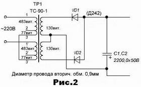
The power supply diagram is shown in Figure 1.
The power transformer of the unit is a rewound network transformer from an old TS-90-1 TV; all turns of the network winding of the transformer are used as the primary winding. The new secondary winding contains 2x65 turns of PETV-2 wire with a diameter of 1.25 mm. If there is no wire of this diameter, you can wind 130 turns of wire with a diameter of 0.9 mm on each of the coils. In this case, the coils are then connected in phase in parallel while maintaining the bridge rectifier circuit. If these coils are connected in series, then you can get rid of two diodes (Fig. 2).
Stabilizer circuit assembled wall-mounted(1 in photo 2). I have capacitors C3 and C4 in the power amplifier housing. The number two indicates an additional adjustable voltage stabilizer for powering the Veda-ChM, assembled on the KREN12A microcircuit. By changing the supply voltage of the radio station itself, you can change the output power of the amplifier within certain limits. The diagram of this stabilizer can be found in the section “Power supplies” - “Voltage stabilizer on KR142EN12A”. The overload indicator works as follows. The voltage on the rectifier filter capacitors C1 and C2 is approximately 37 volts, given that the output voltage is 24V, the voltage between points 1 and 2 will be in the region of 13 volts, which is not enough to break down the zener diodes VD5, VD6, since their total stabilization voltage is 15V . When “short”, the voltage between these points will increase, current will flow through the zener diodes and the HL1 LED will light up, and the HL2 LED will go out. Please note that on the “ground” there are collectors of powerful transistors, which is simply very convenient, placing the transistors directly on the body of the product. The power supply and power amplifier hang on the attic wall under the antenna, which significantly reduces power loss in the cable. Goodbye. K.V.Yu.
This diagram represents simplest block power supply on transistors, equipped with short circuit protection (short circuit). Its diagram is shown in the figure.
Main parameters:
- Output voltage - 0..12V;
- The maximum output current is 400 mA.
The scheme works as follows. The input voltage of the 220V network is converted by a transformer to 16-17V, then rectified by diodes VD1-VD4. Filtering of rectified voltage ripples is carried out by capacitor C1. Next, the rectified voltage is supplied to the zener diode VD6, which stabilizes the voltage at its terminals to 12V. The remainder of the voltage is extinguished by resistor R2. Next, the voltage is adjusted by variable resistor R3 to the required level within 0-12V. This is followed by a current amplifier on transistors VT2 and VT3, which amplifies the current to a level of 400 mA. The load of the current amplifier is resistor R5. Capacitor C2 additionally filters output voltage ripple.
This is how protection works. In the absence of a short circuit at the output, the voltage at the terminals of VT1 is close to zero and the transistor is closed. Circuit R1-VD5 provides a bias at its base at a level of 0.4-0.7 V (voltage drop across open p-n diode transition). This bias is enough to open the transistor at a certain collector-emitter voltage level. As soon as a short circuit occurs at the output, the collector-emitter voltage becomes different from zero and equal to the voltage at the output of the unit. Transistor VT1 opens, and the resistance of its collector junction becomes close to zero, and, therefore, at the zener diode. Thus, zero input voltage is supplied to the current amplifier; very little current will flow through transistors VT2, VT3, and they will not fail. The protection is turned off immediately when the short circuit is eliminated.
Details
The transformer can be any with a core cross-sectional area of 4 cm 2 or more. The primary winding contains 2200 turns of PEV-0.18 wire, the secondary winding contains 150-170 turns of PEV-0.45 wire. A ready-made frame scan transformer from old tube TVs of the TVK110L2 series or similar will also work. Diodes VD1-VD4 can be D302-D305, D229Zh-D229L or any with a current of at least 1 A and a reverse voltage of at least 55 V. Transistors VT1, VT2 can be any low-frequency low-power ones, for example, MP39-MP42. You can also use more modern silicon transistors, for example, KT361, KT203, KT209, KT503, KT3107 and others. As VT3 - germanium P213-P215 or more modern silicon high-power low-frequency KT814, KT816, KT818 and others. When replacing VT1, it may turn out that short-circuit protection does not work. Then you should connect another diode (or two, if necessary) in series with VD5. If VT1 is made of silicon, then it is better to use silicon diodes, for example, KD209(A-B).
In conclusion, it is worth noting that instead of those indicated in p-n-p scheme transistors can be used with similar parameters npn transistors(not instead of any of VT1-VT3, but instead of all of them). Then you will need to change the polarity of the diodes, zener diode, capacitors, diode bridge. At the output, accordingly, the polarity of the voltage will be different.
List of radioelements
| Designation | Type | Denomination | Quantity | Note | Shop | My notepad |
|---|---|---|---|---|---|---|
| VT1, VT2 | Bipolar transistor | MP42B | 2 | MP39-MP42, KT361, KT203, KT209, KT503, KT3107 | Search in Fivel | To notepad |
| VT3 | Bipolar transistor | P213B | 1 | P213-P215, KT814, KT816, KT818 | Search in Fivel | To notepad |
| VD1-VD4 | Diode | D242B | 4 | D302-D305, D229Zh-D229L | Search in Fivel | To notepad |
| VD5 | Diode | KD226B | 1 | Search in Fivel | To notepad | |
| VD6 | Zener diode | D814D | 1 |
Many homemade units have the disadvantage of lacking protection against power reverse polarity. Even an experienced person can inadvertently confuse the polarity of the power supply. And there is a high probability that after this Charger will fall into disrepair.
This article will discuss 3 options for reverse polarity protection, which work flawlessly and do not require any adjustment.
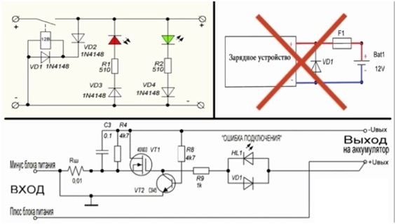
Option 1
This protection is the simplest and differs from similar ones in that it does not use any transistors or microcircuits. Relays, diode isolation - that’s all its components.
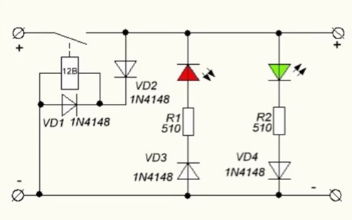
The scheme works as follows. The minus in the circuit is common, so the positive circuit will be considered.
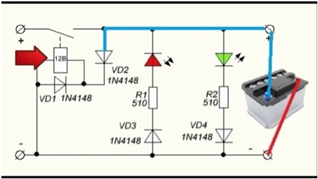
If there is no battery connected to the input, the relay is in the open state. When the battery is connected, the plus is supplied through the diode VD2 to the relay winding, as a result of which the relay contact closes and the main charging current flows to the battery.
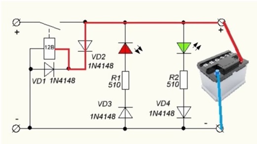
At the same time the green light turns on led indicator, indicating that the connection is correct.
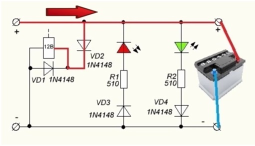
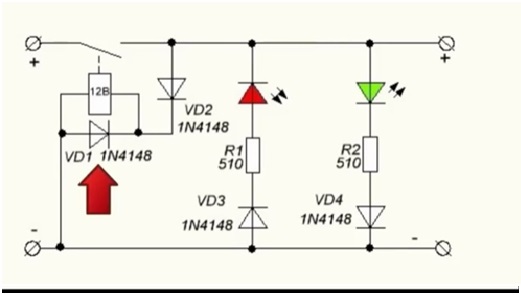
And if you now remove the battery, then there will be voltage at the output of the circuit, since the current from the charger will continue to flow through the VD2 diode to the relay winding.
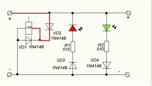
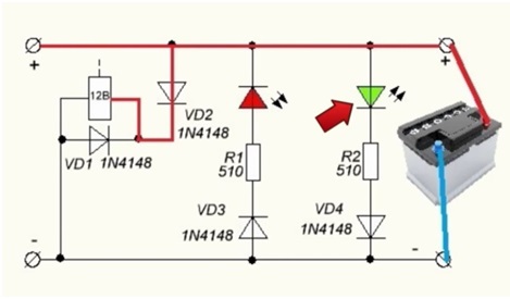
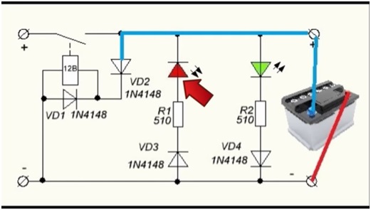
If the connection polarity is reversed, the VD2 diode will be locked and no power will be supplied to the relay winding. The relay will not work.
In this case, the red LED will light up, which is intentionally connected incorrectly. It will indicate that the polarity of the battery connection is incorrect.
Diode VD1 protects the circuit from self-induction that occurs when the relay is turned off.
If such protection is implemented in a car battery charger, it is worth taking a 12 V relay. The permissible relay current depends only on the power of the charger. On average, it is worth using a 15-20 A relay.

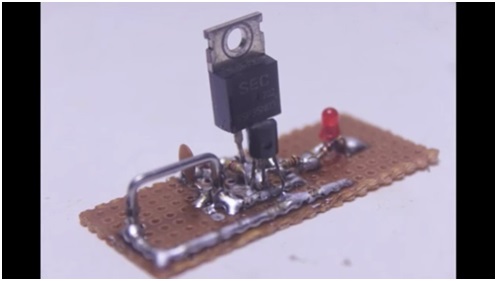
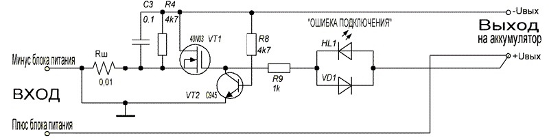
This scheme still has no analogues in many respects. It simultaneously protects against power reversal and short circuit.
The operating principle of this scheme is as follows. During normal operation, the plus from the power source through the LED and resistor R9 opens field-effect transistor, and the minus through the open transition of the “field switch” goes to the output of the circuit to the battery.
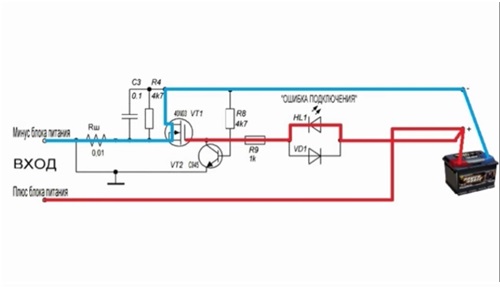
When a polarity reversal or short circuit occurs, the current in the circuit increases sharply, resulting in a voltage drop across the “field switch” and across the shunt. This voltage drop is enough to trigger the low-power transistor VT2. Opening, the latter closes the field-effect transistor, closing the gate to ground. At the same time, the LED lights up, since power for it is provided by the open junction of transistor VT2.
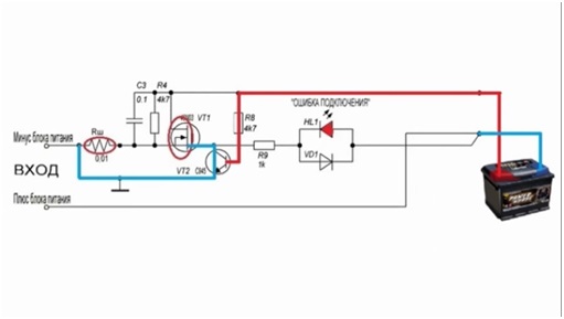
Due to its high response speed, this circuit is guaranteed to protect the charger from any output problem.
The circuit is very reliable in operation and can remain in a protected state indefinitely.
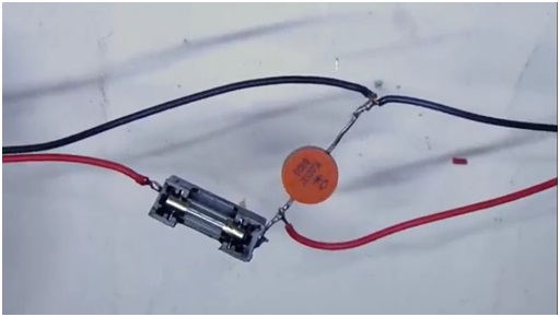
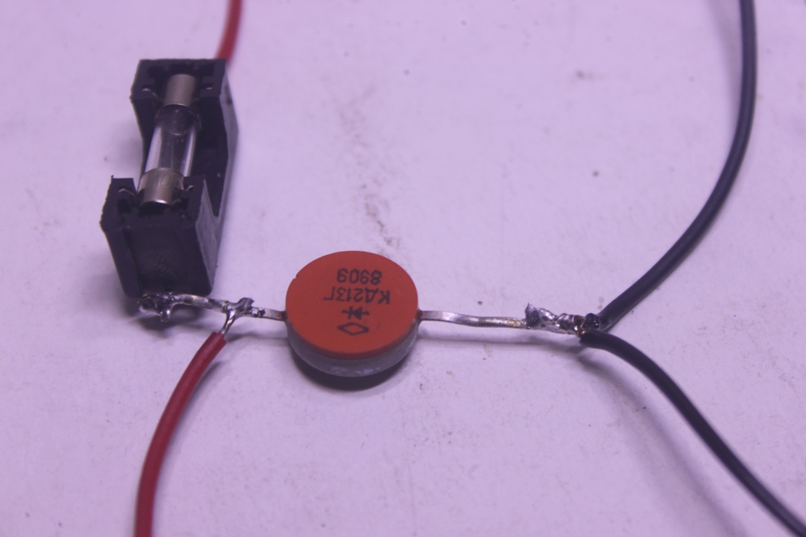
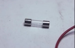
This is special simple circuit, which can hardly even be called a circuit, since it uses only 2 components. This is a powerful diode and fuse. This option is quite viable and is even used on an industrial scale.
Power from the charger is supplied to the battery through the fuse. The fuse is selected based on the maximum charging current. For example, if the current is 10 A, then a 12-15 A fuse is needed.
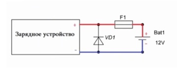
The diode is connected in parallel and is closed during normal operation. But if the polarity is reversed, the diode will open and a short circuit will occur.
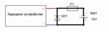
And the fuse is the weak link in this circuit, which will burn out at the same moment. After this you will have to change it.
The diode should be selected according to the datasheet based on the fact that its maximum short-term current was several times greater than the fuse combustion current.

This scheme does not provide 100% protection, since there have been cases when the charger burned out faster than the fuse.
Bottom line
From an efficiency point of view, the first scheme is better than the others. But in terms of versatility and responsiveness, the best option– this is scheme 2. Well, the third option is often used on an industrial scale. This type of protection can be seen, for example, on any car radio.

All circuits, except the last one, have a self-healing function, that is, operation will be restored as soon as the short circuit is removed or the polarity of the battery connection is changed.
Attached files: