Entertaining schemes
An original selection of circuits and entertaining solutions from amateur radio practice, aimed mainly at the novice electronics engineer
Magnetic levitation looks amazing. You can make a circuit for such a device yourself and with your own hands. In this article we will consider simplest option magnetic levitation device diagrams. You will spend no more than two hours on the assembly itself.
Of course you can just start it as pet an ordinary rooster and he is guaranteed to wake you up, but you can put together this simple entertaining diagram.
The dawn alarm clock circuit is made on three digital chips K561LA7. A phototransistor is used as a photo sensor. The phototransistor and resistance R1 are a voltage divider. The sensitivity of the phototransistor is adjusted by selecting the value of R1; the higher it is, the better the sensitivity to morning dawn. Capacitance C1 is used to prevent false triggering of the circuit from random flashes of light. The larger it is, the lower the probability of the circuit triggering due to random lighting

Logic elements DD1.1 and DD1.2 of the K561LA7 microcircuit contain a Schmitt trigger, which sets the switching of the logical level when the specified light level of the phototransistor is reached, and DD1.3 inverts the signal. To switch an RS trigger assembled from logical “cubes” DD2.1 and DD2.2, a short pulse shaper is built on a chain of radio components R5, C3, VD1.
With the morning dawn, the luminous flux also increases sharply in the resistance of the photosensor, so at the tenth output of DD1.3 there will be a logical zero in and the chain R5, C3, VD1 will form a short pulse based on the difference. The RS trigger will switch to another state and a logical one level will appear at the output of DD2.3, starting the AF generator on elements DD2.4, DD3.1-DD3.4.
To turn off the alarm, you need to press and hold the switch button for 15 seconds. When pressed, the sound will disappear immediately, but if the button is released earlier it will start again. Silencing the sound is circuitry associated with the discharge of the previously charged capacitor C5 through resistance R6. At the end of the capacitor discharge process, the RS trigger will return to its original state, thereby blocking further sound of the sound generator.
555 is a series of the legendary timer, which became one of the first integrated microassemblies. It contains about 20 transistors and is used to operate in two modes. In direct timer and rectangular pulse generator mode.
In fact, everything is much simpler; inside the key fob there is a small electronic circuit responsive to any loud noise, including the whistle.
The circuit emits an intermittent beep for a few seconds after a person makes a loud whistle from a distance of no more than seven meters. The first two inverters of the K561LN2 microcircuit are used to process electrical impulses generated by a miniature microphone of the Sosna type. The pre-amplifier circuit is built on the DD1.1 element, and the 1.8 kHz frequency filter is made on the DD1.2 element. The filter eliminates triggering from unwanted sound interference.
Next, the amplified and filtered signal goes to the input of a Schmitt trigger assembled on elements DD1.3 and DD1.6 of the same microcircuit, which changes the continuously changing signal into a set square pulse. The output signal from the trigger controls the sound generator on DD1.4 and DD1.5 and through the first transistor the sound signal reaches the ZP-1 piezoceramic emitter. The sound tone can be adjusted by selecting capacitor C5.
The generator is assembled according to a symmetrical multivibrator circuit, in one of the circuits feedback which the voice coil of the dynamic head of direct radiation BA1 is turned on.
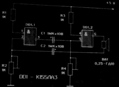
This is how the device works. Let's say that at some point in time there is a logical level of 1 at the output of element DD1.1. Due to this, capacitor C7, connected through resistor R4 to common bus, charging. The charging current creates a voltage drop across this resistor, perceived by element DD1.2 as level 1. At the same time, level 0 is set at its output and capacitor C2 is discharged. As capacitor C1 charges, the voltage drop across resistor R4 decreases. When this value becomes less than a certain value, element DD1.2 switches and level 1 at its output creates a charging current for capacitor C2, passing through the resistance of voice coil BA1 and resistor R2. The voltage drop across this resistor sets the output of element DD1.1 to level 0, and capacitor C1 is discharged. As capacitor C2 charges, the voltage across resistor R2 decreases to the switching threshold of element DD1.1, as a result of which level 1 appears at its output and capacitor C1 begins to charge. In this case, the output of element DD1.2 is set to level 0 and capacitor C2 is discharged. Then the cycle repeats. The charge/discharge current of capacitor C2, passing through voice coil BA1, is converted into sound.
Setting up the generator comes down to setting the required sound tone by selecting the resistance of resistors R1 and R2.
The device can use dynamic heads of any type with a voice coil resistance of 4...8 Ohms and integrated circuits K155LA1, K155LA4, K155LN1, K155LA12.
The following device can be used as a hazard warning light or horn for a mountain bike. It is a two-tone siren and consists of a clock generator on elements DD1.1-DD1.3, two tone generators (the first on elements DD2.1, DD2.2 and the second on elements DD2.3, DD2.4), a matching stage with power amplifier based on element DD1.4 and transistor VT1.
 >
>
The tone generators that determine the pitch of the siren are controlled by a clock generator as follows. Let us assume that at some point in time there is a level of 0 at the output of element DD1.2. Then the output of element DD1.3 will be level 1, which goes to the inputs of elements DD2.1, DD2.2 of the first tone generator. The generator is excited, and the signal from its output goes to the input of the matching stage on element DD1.4. To the second input of this element
Level 1 comes from the output of the second tone generator. This happens because level 0 of the output of element DD1.2 arrives at the inputs of elements DD2.3, DD2.4, causing the appearance of level 1 at their outputs. Arriving at the input of the matching stage from the second tone generator, level 1 allows the signal to pass to its output from the first tone generator, which is amplified by transistor VT1 and converted by dynamic head BA1 into sound waves.
When the signal levels at the outputs of elements DD1.2 and DD1.3 change to the opposite, the second tone generator is turned on, and the first is turned off. Thus, with the operating frequency of the clock generator, the frequency of the sound reproduced by the dynamic head BA1 will also change.
Setting up the device comes down to setting the frequencies of the clock generators with resistors R3, R4 and R5, R6 and adjusting the frequency of the clock generator with resistor R1. You can use transistors KT603, KT608, KT640, etc. with any letter indices and a dynamic head with a voice coil resistance of 4...8 Ohms.
The device, the diagram of which is shown below, when installed on a bicycle, will increase traffic safety. It is designed to control direction indicators and emergency stop signals.

The generator circuit based on elements DD1.1-DD1.3 is familiar to you (see p. 32) and does not need any explanation. Therefore, let's consider the operation of the device as a whole.
When one of the buttons SB1, SB2 is pressed, the supply voltage is supplied to one of the power amplification stages on transistors VT1 or VT2. At the same time, through the corresponding diode VD1 or VD2, power is supplied to the integrated circuit DD1, and the generator begins to operate.
From the output of the generator, a signal with a frequency of about 1 Hz is supplied through resistor R3 to the bases of transistors VT1, VT2. The transistor to which the supply voltage is supplied also opens at the same frequency. As a result, the turn signal lamp (HL1 or HL2), connected to the collector circuit of this transistor, flashes with the same frequency. The second lamp does not light up at this time, since the corresponding diode is switched in the opposite direction and prevents the passage of current to the second power amplification stage.
If you press one of the buttons SB1 or SB2 with the contacts of switch SA1 closed, the supply voltage will be supplied to both amplification stages and both lamps will begin to flash, signaling an emergency stop.
The device is operated under rather harsh conditions (temperature, humidity, vibration, etc.), so please note Special attention on the quality of installation and protection of the board from external influences. The power source for this device can be two A3336 batteries connected in series, or a standard bicycle dynamo connected to it through a power amplifier.
Regarding the application in the device electronic elements, then the integrated circuit K155LN1 can be replaced with K155LAZ, K155L N2, K155LNZ. Transistors - any, medium power with conductivity like p-p-p. Signal lamps operate in a pulsed mode, so they operating voltage 2.5...5 V.
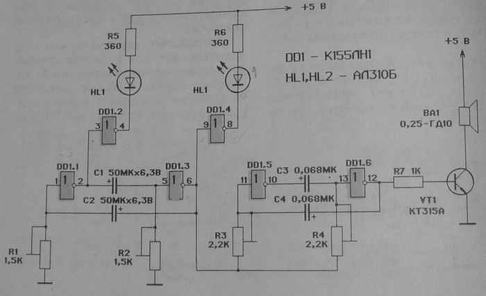
The device, the diagram of which is shown in the figure, will allow you to “revive” a ship or car model with an electric drive. A clock generator with an operating frequency of about 1 Hz is assembled on elements DD1.1, DD1.2, resistors R1, R2 and capacitors C1, C2, which controls the tone generator (DD1.5, DD1.6, R3, R4, C3, C4), operating at a frequency of about 1 kHz. In addition, the clock generator controls the frequency of lighting of the LEDs HL1 and HL2 synchronously with the change in the frequency of the tone generator.
Let's talk about tone generator control in more detail. In this circuit, resistors R3, R4 are connected to the output of the clock generator. When the voltage levels at the output of element DD1.3 change, the voltage levels on capacitors C3, C4 and, consequently, their charge/discharge time and the frequency of the tone generator also change.
Setting up the device comes down to setting the operating frequencies of the clock and tone generators using resistors R1, R2 and R3, R4.
As for the circuit elements, it is possible to use any logical elements with which you can implement the negation function. Transistor VT1 can be of type KT603, KT608, etc. LEDs can be
replaced by incandescent lamps SMN 6.3-20 (in this case, resistors R5, R6 can be excluded from the circuit) or LEDs of another type.
Any type of dynamic head with a voice coil resistance of 4...8 ohms.
If desired, you can install a simple color and music attachment in a cassette recorder or transistor receiver. Its diagram is shown in the figure.
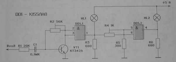
The signal coming from the output of the corresponding device is fed to the base of transistor VT1, which acts as a matching amplifier. At certain levels of input signals, elements DD1.1 and DD1.2 begin to operate and lamps HL1, HL2 light up.
Setting up the set-top box comes down to setting resistors R2 and R4 to operating modes in which they are on the verge of catching fire.
By assembling two such circuits on one board, you will get a color and music attachment for a stereophonic device. Additionally, this device can be used as peak level indicators.
The device is mounted inside your device and connected through a parametric stabilizer to the internal power source. The lamps are placed on the front panel and covered with light filters, the color of which can be chosen to suit your taste.
A diagram of a device designed to create “running fire” or “running shadow” lighting effects is shown in the figure. Based on it, you can create various light signs, decorate a Christmas tree, illuminate display boards, etc.

The circuit is a self-oscillator made of cells included in a ring - inverters, consisting of a resistor, capacitor, transistor and a logical element. For example, one of the cells is R5, C3, VT3, DD1.4. To increase the switching time, an integrating circuit is introduced into each cell. Transistors at the inputs of inverters have a relatively large input impedance, which provides the required signal delay time without increasing the parameters of the elements of the integrating circuit.
The operation of the device is as follows. Let's say that when power is applied, the output of inverter DD1.2 is set to a logical level of 1. In this case, capacitor C2 begins to charge through the resistance of resistor R3. The charging time of the capacitor depends on the capacitance of the capacitor and the resistance of the specified resistor. When the voltage on the capacitor increases to a level of 0.5...0.7 V, transistor VT2 opens and level 0 is supplied to the input of inverter DD1.3, and level 1 appears at its output. At the same time, capacitor C3 begins to charge, and the process is repeated. Thus, after a time equal to the product of the number of generator cells and the delay time of the signal through one cell, level 1 will appear at the output of element DD1.1. Having arrived at the input of element DD1.2, it causes level 0 to appear at its output. In this case, LED HL1 lights up, and capacitor C2 is discharged through resistor R3, the output resistance of element DD1.2 and the emitter junction of transistor VT2. When the capacitor is discharged, transistor VT2 closes and level 1 is supplied to the input of element DD1.3, causing level 0 to appear at its output, after which LED HL2 lights up, and capacitor C3 begins to discharge. Inverters DD1.3-DD1.6 switch in the same way (LEDs HL3-HL6 turn on accordingly), after which level 0 at the output of element DD1.1 will cause level 1 to appear at output DD1.2 and the cycle will repeat. Thus, during operation of the circuit, all LEDs are sequentially lit and extinguished.
You can modify the circuit by changing the number of cells in the ring. In this case, part of the circuit, including resistor R1, capacitor C 7, transistor VT1 and logic elements DD1.1, DD1.2, cannot be changed.
The device, the diagram of which is shown in the figure, allows you to realize a sound effect reminiscent of a chicken clucking. It consists of a clock generator, two sound generators and a power amplifier based on transistor VT2.
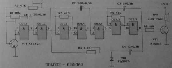
The clock generator is assembled on transistor VT1 and elements DD1.1, DD1.2. Its frequency is determined by the resistance of resistors R1 and R2 and the capacitance of capacitor C1.
The use of a transistor in a clock generator is due to the fact that in order to obtain long-duration pulses it is necessary to increase the input resistance of the inverter DD1.1. It should be borne in mind that the gain of transistor VT1 also affects the duration of the pulses. Depending on its value, the resistance of resistor R2 may be greater or less than that indicated in the diagram. Resistor R1 is used to adjust the pulse duration, and resistor R2 is used to adjust the pause between them.
The clock generator controls the operation of a generator assembled on elements DD1.3, DD1.4, the pulse repetition rate of which is 5 Hz. It is determined by the resistance of resistor R3 and the capacitance of capacitor C2. In turn, through the DD2.1 inverter, the clock generator controls the operation of the audio frequency signal generator on elements DD2.2, DD2.3. The power amplifier is assembled on a transistor VT2, the load of which is the voice coil of the dynamic head with a resistance of 4...8 Ohms, a power of 0.1...0.5 W.
When the supply voltage is applied, the clock generator begins to operate, generating pulses of positive polarity with a duration of 2...2.5 s with pauses of 1 s. From the output of this generator, pulses arrive at the input of element DD1.3 and start a second generator, which during this time forms packs of 4 - 5 pulses, which are inverted and start the sound generator. It, in turn, produces 4 - 5 sequences of pulses of sound frequencies, similar to the sounds of “kud-kud-kud”.
At the same time, the signal from the output of the clock generator through resistor R4 periodically unlocks and closes diode VD1, through which capacitor C4 is charged, which affects the frequency of the sound generator. This produces a sound similar to “yes.” When the generators are configured correctly, the clucking of a chicken is imitated.
For those of you who build radios or amplifiers in addition to digital electronics, an indispensable assistant In their repair and adjustment, you may find a probe for checking low-frequency and high-frequency paths. It contains two generators: low-frequency on elements DD1.3, DD1.4 and high-frequency on elements DD2.1, DD2.2. The probe has two outputs with the ability to adjust the signal amplitude on each of them from 0 to 2 V.
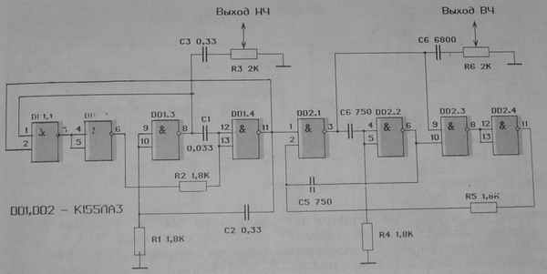
The generators are assembled according to the circuit of symmetrical multivibrators, to the outputs of which trigger units are connected. The need to use the latter is due to the fact that when power is applied, the multivibrator, for example, on elements DD1.3, DD1.4, will not start, since the charging current of capacitors C1 and C2, depending on their capacitance and the resistance of resistors R1, R2, will be quite small. Therefore, the voltage on none of the resistors can exceed level 1 and levels 1 will be present at both outputs of the multivibrator. When the trigger nodes are connected, level 0 appears at the output of element DD1.1, and level 1 appears at the output of element DD1.2. As a result, At the output of element DD1.4, a logical level of 0 appears and the multivibrator starts.
This node does not affect the operation of the multivibrator in steady state, since level 0 will always be present at one of the inputs of element DD1.1 and, accordingly, at the output of element DD1.2, which is equivalent to connecting resistor R2 to the common bus. The second multivibrator is launched in a similar way.
Low frequency signals from the output of the first multivibrator trigger the second multivibrator. At its output, pulses are formed, modulated in amplitude by a low-frequency signal. To eliminate the DC component, they are supplied to the probe output through appropriate capacitors.
If the radio circuits are powered from batteries, then it is necessary to monitor the degree of their charge. The simple device offered here will help you with this. It will automatically ensure that the voltage of the autonomous power source is within acceptable limits. The service life of batteries and their energy parameters depend on this. Reducing the voltage on the power rails of devices using digital integrated circuits below a certain level (4.5 V) can cause them to malfunction.
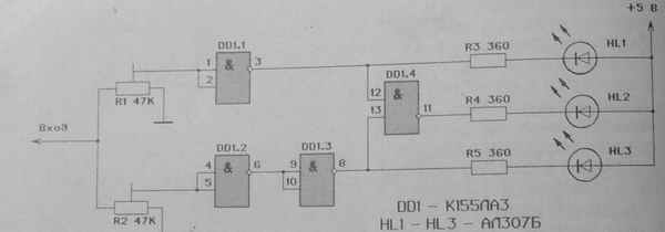
The control device has two channels: the first - on element DD1.1, the second - on elements DD1.2, DD1.3. The first channel is configured so that when the input voltage is more than 5.25 V, the DD1.1 element receives a logical 1 level from resistor R1. In this case, the DD1.1 output is set to level 0, which turns on the HL1 LED and prohibits the operation of the DD1.4 element.
The second channel is triggered when the voltage at the input of the control device is less than 4.75 V. In this case, level 0 is set at the input of element DD1.2, and level 1 at the input of element DD1.3. Level 0 at the output of the element turns on the HL3 LED and prohibits the operation of the element DD1.4.
If the input voltage of the control device is 4.75...5.25 V, then the outputs of elements DD1.1 and DD1.3 are level 1, and the output of element DD1.4 is level 0, which turns on the HL2 LED. Thus, the device provides constant visual information about the voltage levels supplied from the power supply to the digital device.
The amateur radio circuit is a device on a single chip of the K561TM2 type, consisting of two triggers. On trigger D1.1. a generator is made that generates pulses with a frequency of 16 Hz. On trigger D1.2. a frequency divider by two is made.
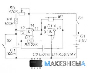
The K561LA7 microcircuit (or its analogs K1561LA7, K176LA7, CD4011) contains four 2I-NOT logic elements (Figure 1). The operating logic of the 2I-NOT element is simple - if both of its inputs are logical ones, then the output will be zero, and if this is not the case (that is, there is a zero at one of the inputs or both inputs), then the output will be one. Chip K561LA7 CMOS logic, this means that its elements are made on field effect transistors, therefore, the input impedance of the K561LA7 is very high, and the energy consumption from the power supply is very low (this also applies to all other microcircuits of the K561, K176, K1561 or CD40 series).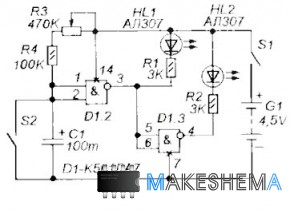 Figure 2 shows a diagram of a simple time relay with LED indication. Time counting begins at the moment the power is turned on by switch S1. At the very beginning, capacitor C1 is discharged and the voltage on it is low (like a logical zero). Therefore, the output D1.1 will be one, and the output D1.2 will be zero. LED HL2 will be lit, but LED HL1 will not be lit. This will continue until C1 is charged through resistors R3 and R5 to a voltage that element D1.1 understands as a logical one. At this moment, a zero appears at the output of D1.1, and a one appears at the output of D1.2.
Button S2 is used to restart the time relay (when you press it, it closes C1 and discharges it, and when you release it, charging C1 starts again). Thus, the countdown begins from the moment the power is turned on or from the moment the S2 button is pressed and released. LED HL2 indicates that the countdown is in progress, and LED HL1 indicates that the countdown has completed. And the time itself can be set using variable resistor R3.
You can put a handle with a pointer and a scale on the shaft of resistor R3, on which you can sign the time values, measuring them with a stopwatch. With the resistances of resistors R3 and R4 and capacitance C1 as in the diagram, you can set shutter speeds from several seconds to a minute and a little more.
The circuit in Figure 2 uses only two IC elements, but it contains two more. Using them, you can make it so that the time relay will sound a sound signal at the end of the delay.
 Figure 3 shows a diagram of a time relay with sound. A multivibrator is made on elements D1 3 and D1.4, which generates pulses with a frequency of about 1000 Hz. This frequency depends on resistance R5 and capacitor C2. A piezoelectric “tweeter” is connected between the input and output of element D1.4, for example, from an electronic watch or a handset, or a multimeter. When the multivibrator is working it beeps.
You can control the multivibrator by changing the logic level at pin 12 of D1.4. When there is zero here, the multivibrator does not work, and the “beeper” B1 is silent. When one. - B1 beeps. This pin (12) is connected to the output of element D1.2. Therefore, the beeper beeps when HL2 goes out, that is, sound alarm turns on immediately after the time relay has completed its time interval.
If you don’t have a piezoelectric “tweeter”, instead of it you can take, for example, a microspeaker from an old receiver or headphones or telephone. But it must be connected through a transistor amplifier (Fig. 4), otherwise the microcircuit can be damaged.

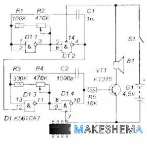
However, if we don’t need LED indication, we can again get by with only two elements. Figure 5 shows a diagram of a time relay that only has an audible alarm. While capacitor C1 is discharged, the multivibrator is blocked by logical zero and the beeper is silent. And as soon as C1 is charged to the voltage of a logical unit, the multivibrator will start working, and B1 will beep. Figure 6 is a diagram of a sound alarm that produces intermittent sound signals. Moreover, the sound tone and interruption frequency can be adjusted. It can be used, for example, as a small siren or apartment bell.
A multivibrator is made on elements D1 3 and D1.4. generating audio frequency pulses, which are sent through an amplifier on transistor VT5 to speaker B1. The tone of the sound depends on the frequency of these pulses, and their frequency can be adjusted by variable resistor R4.
To interrupt the sound, a second multivibrator is used on elements D1.1 and D1.2. It produces pulses of significantly lower frequency. These pulses arrive at pin 12 D1 3. When the logical zero here, the multivibrator D1.3-D1.4 is turned off, the speaker is silent, and when it is one, a sound is heard. This produces an intermittent sound, the tone of which can be adjusted by resistor R4, and the interruption frequency by R2. The sound volume largely depends on the speaker. And the speaker can be almost anything (for example, a speaker from a radio, telephone, radio receiver, or even acoustic system from the music center).
Based on this siren you can make burglar alarm, which will turn on every time someone opens the door to your room (Fig. 7).
Searching for treasures, ancient relics and other interesting things is a fairly popular hobby for many, along with fishing or hunting. This type of recreation can also be considered active, and for some, a metal detector is quite a good tool for making money, because you can find quite a lot in the ground a large number of ferrous metals that are valued today. After all, there is a proverb that “we walk on money.”
In stores, even for a metal detector that is not very powerful, they sometimes charge decent money. This article will talk about how you can assemble a metal detector with your own hands. This requires minimal skills in working with electronics and a small investment (in comparison with buying a new metal detector).
Materials and tools for assembly:
- K561LA7 microcircuit or its equivalent;
- low-power low-frequency transistor (KT315, KT312, KT3102 are suitable, analogues: BC546, BC945, 2SC639, 2SC1815 and so on)
- any low-power diode (for example kd522B, kd105, kd106...);
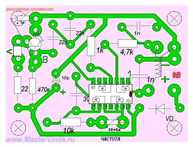
- three variable resistors (4.7 kOm, 6.8 kOm, 10 kOm with switch);
- five fixed resistors (22 Om, 4.7 kOm, 1.0 kOm, 10 kOm, 470 kOm);]
- five ceramic or mica capacitors (1000 pf - 2 pcs., 22 nF - 2 pcs., 300 pf);
- one electrolytic capacitor (100.0 uF x 16V);
- PEV or PEL type wire with a diameter of 0.6-0.8 mm;
- headphones from the player (or any low-impedance ones);
- 9V battery.
Metal detector manufacturing process:
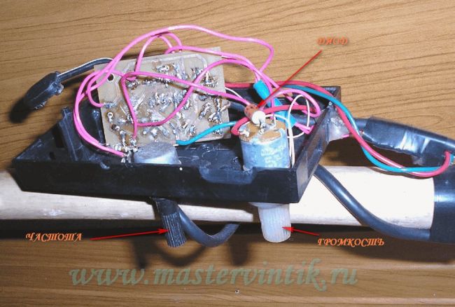
Step one. Housing and appearance devices
Due to the fact that searches often take place among branches, grass or in wet weather, the device must be reliably protected from the influence of all these factors. You can use a soap or shoe polish box as a housing for electronics. The main thing is that the electronic part is reliably protected.


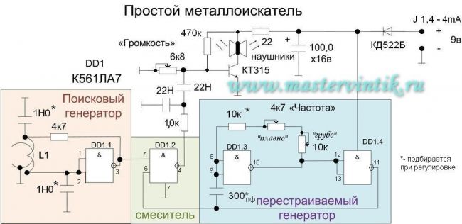
It is important to know that if you do not connect variable resistors(their housing) with a minus board, the device will generate interference. If everything is done correctly and a high-quality coil is made, no problems will arise during the operation of the device. When you turn on the metal detector, a characteristic squeak should immediately appear in your headphones; it should respond to the frequency control knob. If this is not observed, then you need to select a 10 kOhm resistor, which is in series with the regulator, or select a 300 pF capacitor in this generator. As a result, you need to align the frequencies of the search and reference generators.
To determine what frequencies the generator emits, you will need an oscilloscope. In total, the operating frequency can be in the range of 80-200 kHz. Measurements are taken on pins 5 and 6 of the K561LA7 microcontroller.
The system also has a protective diode. It is needed to protect the electronics from the battery being turned on incorrectly.
Step two. Making a search coil
The coils are wound on mandrels with a diameter of about 15-25 cm. A bucket or shuttle made of wire or plywood can be used as a form. The smaller the coil, the less sensitivity it will have, it all depends on the purpose for which the metal detector will be used.

As for the wire, it can be a wire in varnish insulation such as PEV or PEL with a diameter of 0.5 to 0.7 mm. This type of wire can be found in old TVs with picture tubes. In total, the coil contains 100 turns, you can wind from 80 to 120. The whole thing is tightly wrapped with electrical tape on top.
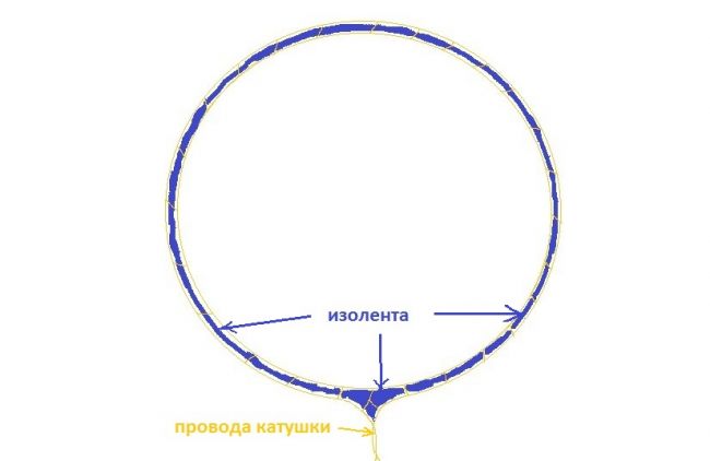
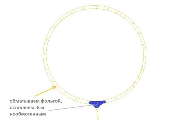
When the coil is wound, a winding of a strip of foil is made on top of it, while you need to leave a section of 2-3 centimeters unwound. Foil can be found in some types of cables; it can also be obtained from chocolate bars by cutting it into pieces.
It is not an insulated wire that is wound on top of the foil, but preferably a tinned one. The beginning of the wire ends up on the coil, and the other end is soldered to the body. The whole thing is again well wrapped with electrical tape on top.

Subsequently, the coil is attached to the dielectric, like option will do non-foil PCB. Well, now the reel can be attached to the holder.

To connect the coil to the circuit, you need to use a shielded wire; the screen is connected to the housing. Similar wires can be used to dub music from a tape recorder. You can also use the bass cord to connect various devices to the TV.
Step three. Checking the metal detector
When the device is turned on, a characteristic noise can be heard in the headphones; the frequency must be adjusted using the regulator. When you bring the coil close to the metal, the noise in the headphones will change.
![]()
You can also alter the circuit in such a way that the metal detector is silent during operation, and the signal will appear only when metal appears under the coil. In this case, the frequency of the noise will indicate the size of the object and at what depth it is located. But, according to the author, with this approach the sensitivity of the metal detector is greatly reduced, and it only detects very large objects.
To obtain zero beats, you need to combine two frequencies.
This is how you can assemble a simple metal detector with your own hands. Of course, you are unlikely to find a real treasure with it, but collecting coins and coins lost on the beach is quite possible. You can make two coils for the device, one for searching for large objects, and the second for searching for small ones.


