First of all, we will deal with the most important element of any system - its heart. For an amplifier, this is, as you may have guessed, a power supply. Let's finalize it following the advice of Nikolai Vasilyevich + add a few tricks of our own.
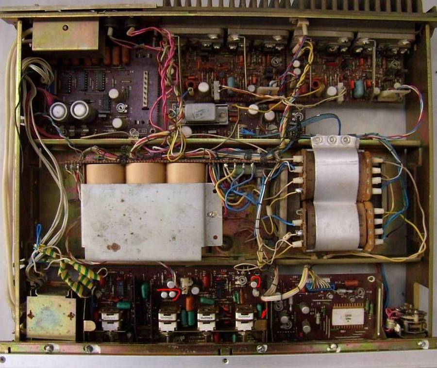
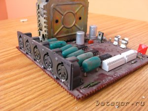
All wires inside are collected with special ties. This is the first time I have seen such precision in Soviet technology. Although, most likely, I simply did not come across such samples.
Unscrew the clamping screws
disconnect the power cable from the preamplifier
display unit, while unfastening the tie
and final amplifiers, while also removing a couple of ties.
That's it, the easy way is over, now you have to pick up a soldering iron. We unsolder the power from the input board. Yes, kids, never solder on the couch.
By the way, I still haven’t figured out where to find the correction amplifier for the player. It seems like a separate block is located on the input board, but at the same time, some additional microcircuit is on the preamplifier. Okay, we'll figure it out as we go. We unsolder the zeros going to the output to the speakers and to the case. Soldering is difficult, my 25 watt soldering iron can barely cope.
Okay, of course, you can also unsolder the transformer and the protection unit, but I’m too lazy, especially since the power supply has already gained more than enough mobility for further manipulations with it. The girl moves onto the table.
Well, let's start by soldering the capacitor into the network circuit to protect our baby from all sorts of unnecessary interference. This one from an old monitor will do just fine.
Let's move on to finalizing the power supply itself. As Nikolai Vasilyevich wrote in his newer article, it is not at all necessary to transfer all power to 31 volts; it is enough to power the terminals to the maximum to get maximum output, and put all other consumers on a 26-volt “diet”. Among other things, this will help avoid many problems, in particular with overheating of resistors in the display unit.
I will not set the zero as Nikolai Vasilyevich advises. Somehow it seems to me that there will be much less tangible benefit than hemorrhoids with new wires. Moreover, the iron case should already protect against interference, if you believe what we were told in physics.
Let's start by swapping the 26 and 31 volt terminals from the transformer to apply more voltage to a more stabilized section. (Although, if you consider that 10,000 uF capacitors will be used, this benefit becomes slightly doubtful, because everything will be in chocolate anyway, but nevertheless)
Swap the wires on both terminals 4 and 5 of the transformer. Now, as expected, more voltage flows through wires of larger cross-section.
We cut out MBM (anti)filter capacitors. I never liked them.
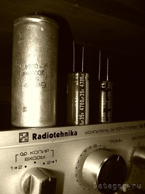
Let's move on to replacing the main "barrels". It's a pity, but they will have to be thrown away. It is unlikely that they have at least a third of the declared capacity left.
As it turns out, the process is much easier if you remove the plastic gasket.
And now we’ll file our 10-milifarad monsters here. Jackcon, of course, is not the most expensive brand, but for our purposes it is just right.
What do we have in the end? The capacity has increased by 5 times, while the volume has decreased by 2. Progress, hello!
And now - the promised trick. We solder a non-polar capacitor type K73-17 in parallel to each direction. Nikolai Vasilyevich does not have this, but according to many close to the topic, this increases the quality of output at high frequencies. Yes, yes, the power supply in an amplifier is a very important sound-forming element! What did you think? The world is not at all what catches your eye at first glance.
After the third turn on, it became clear that the diodes of the small rectifier were smoking. When measuring, two of them turned out to be pierced. Who knows, maybe something went wrong during the first turn-on, or 10 millifarads is too much of a burden for them, but, in any case, there is no going back. There are no diodes either, so I have to run to the store tomorrow.
But this minor trouble will not stop us! Muahaha! We continue to test the larger rectifier.
At first, the author was very surprised why the larger rectifier produces 66 volts instead of the expected 31. But then he realized to look at the diagram and saw that it says -31 and +31, i.e. the total potential difference is 62 volts, which is the same as 66, only under load.
Well, hallelujah, brothers and sisters, the engine is almost ready to carry us into a bright future filled with divine sound. There are a couple of small ones left, but necessary details, and we will move on to the most interesting part of our story. Amen.
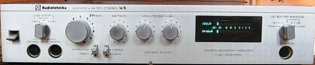
Many people still have “Radiotekhnika U-101-stereo” power amplifiers from Soviet times. The article below discusses its diagram, characteristics and modifications.
MZF with low nonlinear distortions
Basic specifications:
- Rated output power at a load of 8 ohms, W ... 25
- Harmonic coefficient, %, no more than ……………….. 0.003
- Output voltage slew rate, V/µs…. at least 40
- Rated input voltage, V……………….. 0.7
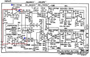
UMZCH consists of a two-stage voltage amplifier (op-amp DA1, DA2) and the power amplifier itself (VT1-VT4). Cascades on op-amps DA1, DA2 are powered from identical sources formed by elements VD1, VD2, R6, R7, C6, C7 and VD3, VD4, R14, R15, C13, C14. The midpoints of these power supplies are connected to a low-resistance voltage divider R5R12R20, connected to the output of the UMZCH, which ensures the supply of tracking potentials to the voltage amplifier stages. Circuits R16C8 and R19C10 filter the voltages supplying the first stages from nonlinear ripples generated by the signal in the power circuits of the output stage.

The cascade on op-amp DA1 is covered by local feedback (R2, R4) and amplifies the signal 10 times. Since the cascade output has a constant voltage of about 1 V, it is separated from the input of op-amp DA2 by capacitor C5. The second stage (DA2) together with the output stage (VT1 - VT4) amplifies the signal voltage only by 2 times. The gain of this op-amp is thus “spent” only on the linearization of the output stage. The output stage is a well-known parallel amplifier. Resistors R17, R18, R25, R26 correct its frequency response in the region higher frequencies. In the output stage, you can use transistors of the series indicated in the diagram with the index G (the static current transfer coefficient of transistors VT3, VT4 must be at least 30). In a voltage amplifier, it is possible to use op-amps K140UD8, K544UD1, but the harmonic coefficient in this case will increase approximately threefold. KS515A zener diodes can be replaced by two D814A zener diodes connected in series.
Improvement of the amplifier "Radio Engineering U-101-stereo"
Y. M. Kogut, Lviv region.
I propose the option of converting the complete amplifier “Radiotekhnika U-101” into a truly high-quality amplifier for a household audio equipment complex. Distinctive features: high technical characteristics and reliability with minimal intervention in the converted device, when all functionality original amplifier.
The complete amplifier “Radiotekhnika U-101” was at one time popular among music lovers, and many such devices are still preserved by their owners. Even a superficial analysis of the circuit points to the ULF-50-8 module as the weakest link of the amplifier. The module does not fully realize the capabilities of the pre-amplifier assembled on K157UD2 microcircuits.
To replace the ULF-50-8 module, an UMZCH with low nonlinear distortion was selected. Its main technical characteristics:
rated output power at a load with a resistance of 8 Ohms, 25 W;
harmonic coefficient in the frequency range 20-20000 Hz 0.03% (0.3% for ULF-50-8);
output voltage slew rate 40 V/µs.
It should be noted the low cost of alteration. I purchased microcircuits and transistors on the market inexpensively, the rest was “at hand”.
There were no problems with attaching the UMZCH output transistors to the Radiotekhnika radiator in accordance with the recommendations. The radiator has four metal plates insulated with mica spacers. There is enough space on each plate for three transistors, no modifications to the heatsink are required.
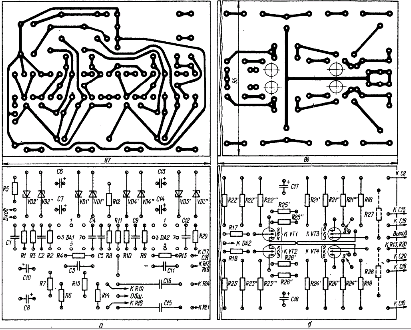
The only problem is the need to reduce printed circuit boards UMZCH, since there is not enough space in Radiotekhnika. Two UMZCHs should be assembled on two printed circuit boards, the width of which should not exceed 60 mm. The drawing of the voltage amplifier board (Fig. 3a) needs to be compacted in width to this size. This is not difficult to do if the K50-6 capacitors are replaced with K50-35 or other small ones. The drawing of the final stage board (Fig. 3.6c) will fit on a 60 mm wide board without changes (drawings are provided).
The first board is made 240 mm long and one voltage amplifier and two final stages are placed on it. Another voltage amplifier is placed on the second board.
The long board is attached to the Radiotekhnika radiator on 15 mm long stands so that it is placed vertically in the amplifier housing. The ULF-50-8 boards are first dismantled. The second voltage amplifier board is attached to a long board on 20 mm long stands on the side wall of the amplifier housing.
The UMZCH is connected to the ±26 V power supply of Radiotekhnika. The supply voltage ±30 V is not used. The output of the UMZCH is connected to the “Radio Engineering” protection board. The signal wires do not need to be confused (the same applies to the input wires).
Correctly assembled and connected UMZCHs begin to work immediately after turning on the power and do not require adjustment. I also recommend replacing the capacitors SZ, C4, C8, C9 on the Radiotekhniki rectifier board. They have probably already lost some of their capacity (dried out), so it is better to replace them with new ones with a capacity of 4000-5600 µF.
All functionality of Radiotekhnika is retained after the modification. The sound of the converted amplifier can be characterized by epithets: clean, transparent, rich with clear localization of sound sources. It's much better than the original amp and noticeably better than the AKAI FD-1 I have.
When operating the converted amplifier at sound speakers with LF heads of type 10GD-30 or 25GD-26, characteristic clicks are heard at high volumes. This occurs due to insufficient rigidity of the caps covering the magnetic gaps of the heads. The caps should be replaced with more rigid ones. The original amplifier has much worse performance, so no clicks were observed.
Literature
1. Amplifier “Radio engineering U-101 stereo”. Manual.
2. Ageev A. UMZCH with small nonlinear distortions//Radio.-1987.-No. 2.-P.26-29.
From the editor. Here are drawings of printed circuit boards and placement of elements published in Radio magazine, to which the author of the article refers.
RADIOAMATOR No. 10, 2001
Popularity: 18,007 views
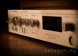
I would like to tell you about my story of repair and modernization of the Radiotekhnika U-101-stereo amplifier. It seems like a completely ordinary amplifier originally from the USSR, but there is some inexplicable appeal in it ( for me personally), which is difficult to explain.
How to describe the feeling when you meet absolutely unknown girl, you meet your gaze, and then for a long time her eyes and silhouette do not leave your memory?... I liked her, she was beautiful, but your destinies are not destined to be intertwined.
When I first saw/heard Radio Engineering I can’t even remember. But it stuck in my memory, and not just a wild desire to buy and listen, no, just a pleasant image. And then the other day the thought materialized and fate gave me RT 101 as a gift. Tired, tormented by everyday life and lack of attention.
I wish my wife didn’t read these lines, otherwise she’ll get jealous and call her crazy
:love: To put up with malfunctions and terrible things technical condition I can’t, I have no peace. Therefore, instead of flowers and sweets for my wife, I regularly buy capacitors, microcircuits, resistors, etc....
I decided to bring RT back to life. To begin with, the following had to be overcome:
1. Transformer hum.
2. The same terrible hum in the speakers.
3. Cotton when turned on and some scary sound when turned off.
4. Signal indicator not working.
5. Noisy regulators.
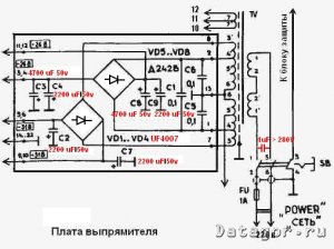
The first step was to replace all electrolytic capacitors. Everything is according to the original ratings, the only thing in the power supply is that the capacity has been slightly increased: 2x2200+ 2x4700 uF to power the final stage (C3, C4, C8, C9 in the diagram). KD209A diodes are replaced with “ultrafast” UF4007.
I will say right away that this operation almost eliminated the first three points of problems.
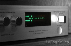
It was not possible to revive the indicator by simply changing the capacitors, but I really wanted to save it... It continued to show the entire scale, without reacting to anything. While clarifying the reasons on the forum, we came to the conclusion ( possibly false) that the K161PP2 microcircuit has failed. Finding one, you understand, is not easy. Easier than a complete indicator.
The world is not without good people(believe in this, do good yourself and the result will not keep you waiting long) and the indicator along with the ULF-P of the latest revision, the one on the same chip, was given to me by the broadest soul man Vasily (Skif on Vegalab). For which I bow to him and be very grateful!!! True, the functionality of the modules was in question.
In the purchased indicator, we had to replace the trimming resistors, which were covered in nail polish and became unusable. The indication of one channel is working!!! But we have a stereo... I didn’t suffer for a long time, but immediately decided to replace the K157UD2. The operation was a success and that unforgettable green sparkle appeared in RT’s eyes again.
Further more.
The sound after restoration was mesmerizing with bass. It would seem that 2x 20 W, and such bass that the windows tremble, the plasterboard partition in the kitchen vibrates, and in the evening, while watching a movie at a volume level below average, the neighbor from downstairs called and asked in a sweet, restrained voice to turn down the volume.
But the happiness did not last long. After reading strangers opinions and reviews about how much better the single-chip pre sounds, less distortion, etc., I decided to change my native one. ( For the sake of the authenticity of the article, I will inform you that it was replaced at the stage of work with the indicator. Before this, the ULF-P of the old revision was listened to for a couple of weeks.) And at first I really heard ( or wanted to hear) all these advantages: “high-end detail”, “clearer scene”, “grainy mids”, etc.
But in the depths of the soul there is no peace, there is no pleasure when listening, only self-deception driven into the head by meaningless terms. This was no longer the girl I knew.
A week of listening was enough to understand that it was necessary to return the original ULF-P on three microcircuits. But here’s the problem, I had already started to burn bridges when I removed one K157UD2 (DA 1.* in the diagram) from the dismantled preamplifier, which was used to repair the indicator. I was puzzled by the search for information, understood in more detail the structure and operation of 101. I came to the conclusion that exclusion from the DA 1.* scheme does not lead to negative consequences. (DA 1.* in the preamplifier serves to match the piezoceramic pickup, for me this is not relevant).
The signal from the source after the input selector is supplied to R9 and R10, respectively. Interstage capacitors C23, C24 were replaced out of harm's way with new non-polar ones. First launch after modernization: a lot of worries and one small hope to return the former voice...
From the first notes of familiar compositions, I realized that the goal had been achieved, the bass lived in 101 again! I don’t know how to describe the sound in a sweeping manner, I’ll simply say: you either like it or you don’t. Now I like it! Thus, as a result of related events, the third version of the pre-amplifier RT 101, two-chip, appeared.
The popping sound in the speakers when turned on was the result of a malfunctioning protection. Extraneous sounds when turning off the amplifier, just like the reaction to turning on/off household appliances in the apartment, were eliminated by installing a noise-suppressing capacitor with a capacity of 1 μF and a voltage of >280V on the contacts of the power switch.
The volume, balance and tone controls are cleaned of dust by air flow and lubricated (Ciatim 201 lubricant).
In addition to the preamplifier, the following changes were made to the RT 101 design:
The original input switch along with the corrector amplifier has been removed.
Instead of the original one, the input selector for three sources is made on a biscuit, which previously served as a “Copier” switch in the amplifier (SA2 on). The switch has 4 pairs of contacts, so it allows you to break even the ground of incoming signals.
Connectors for connecting sources are standard RCA, two pairs per back wall and one for “hot” connection of sources on the front panel (in places where the “five” connections of tape recorders previously rested). After removing unused switches and connectors, the holes on the front panel are closed with aluminum-look plugs (Dubond material).
IN result The amplifier has lost its value for museums, but is compatible with modern sources and works.
This completes the first part of the work. The second is more complex, since it was decided to refine the body and give it a final “gloss”. I plan to veneer top cover, make a new bottom, properly design the back panel with connectors. Which I will definitely tell dear readers about in the second part of the article.
It was very widely used by many music lovers and many still have it today.
However, even a superficial analysis of the circuit points to the ULF-50-8 module as the weakest link of the amplifier. The module does not fully realize the capabilities of the pre-amplifier assembled on K157UD2 microcircuits.
I suggest option for remaking a complete amplifier Radiotekhnika U-101 into a truly high-quality amplifier for a household audio equipment complex. Distinctive features: high technical characteristics and reliability with minimal intervention in the converted device, when all the functionality of the original amplifier is preserved.
To replace the ULF-50-8 module, an UMZCH with low nonlinear distortion was selected. Its main technical characteristics:
rated output power at a load with a resistance of 8 Ohms, 25 W;
harmonic coefficient in the frequency range 20-20000 Hz 0.03% (0.3% for ULF-50-8);
output voltage slew rate 40 V/µs.
Amplifier circuit for reworking Radio Engineering U101
The UMZCH consists of a two-stage voltage amplifier (op-amp DA1, DA2) and the power amplifier itself (VT1-VT4). Cascades on op-amps DA1, DA2 are powered from identical sources formed by elements VD1, VD2, R6, R7, C6, C7 and VD3, VD4, R14, R15, C13, C14. The midpoints of these power supplies are connected to a low-resistance voltage divider R5R12R20, connected to the output of the UMZCH, which ensures the supply of tracking potentials to the voltage amplifier stages. Circuits R16C8 and R19C10 filter the voltages supplying the first stages from nonlinear ripples generated by the signal in the power circuits of the output stage.
There were no problems with attaching the UMZCH output transistors to the Radiotekhnika radiator in accordance with the recommendations. The radiator has four metal plates insulated with mica spacers. There is enough space on each plate for three transistors, no modifications to the heatsink are required.

The only problem is the need to reduce the UMZCH printed circuit boards, since there is not enough space in Radiotekhnika. Two UMZCHs should be assembled on two printed circuit boards, the width of which should not exceed 60 mm. The drawing of the voltage amplifier board (Fig. 3a) needs to be compacted in width to this size. This is not difficult to do if the K50-6 capacitors are replaced with K50-35 or other small ones. The drawing of the final stage board (Fig. 3.6c) will fit on a 60 mm wide board without changes (drawings are provided).
The first board is made 240 mm long and one voltage amplifier and two final stages are placed on it. Another voltage amplifier is placed on the second board.
The long board is attached to the Radiotekhnika radiator on 15 mm long stands so that it is placed vertically in the amplifier housing. The ULF-50-8 boards are first dismantled. The second voltage amplifier board is attached to a long board on 20 mm long stands on the side wall of the amplifier housing.
The UMZCH is connected to the ±26 V power supply of Radiotekhnika. The supply voltage ±30 V is not used. The output of the UMZCH is connected to the “Radio Engineering” protection board. The signal wires do not need to be confused (the same applies to the input wires).
Correctly assembled and connected UMZCHs begin to work immediately after turning on the power and do not require adjustment. I also recommend replacing the capacitors SZ, C4, C8, C9 on the Radiotekhniki rectifier board. They have probably already lost some of their capacity (dried out), so it is better to replace them with new ones with a capacity of 4000-5600 µF.
All functionality of Radiotekhnika is retained after the modification. The sound of the converted amplifier can be characterized by epithets: clean, transparent, rich with clear localization of sound sources. It's much better than the original amp and noticeably better than the AKAI FD-1 I have.
When the converted amplifier is used on speakers with LF heads such as 10GD-30 or 25GD-26, characteristic clicks are heard at high volumes. This occurs due to insufficient rigidity of the caps covering the magnetic gaps of the heads. The caps should be replaced with more rigid ones. The original amplifier has much worse performance, so no clicks were observed.
Y. M. Kogut, Lviv region.
Literature
1. Amplifier “Radio engineering U-101 stereo”. Manual.
2. Ageev A. UMZCH with low nonlinear distortions//Radio.-1987. -No. 2.-P.26-29.
Here are drawings of printed circuit boards and placement of elements published in Radio magazine, to which the author of the article refers.
RADIOAMATOR No. 10, 2001