When using an electric motor in tools, one of the serious problems is adjusting the speed of their rotation. If the speed is not high enough, then the tool is not effective enough.
If it is too high, then this leads not only to a significant waste of electrical energy, but also to possible burnout of the tool. If the rotation speed is too high, the operation of the tool may also become less predictable. How to fix it? For this purpose, it is customary to use a special rotation speed controller.
Motor for power tools and household appliances usually falls into one of 2 main types:
- Commutator motors.
- Asynchronous motors.
In the past, the second of these categories had greatest distribution. Now, approximately 85% of engines that are used in electrical instruments, household or kitchen appliances, belong to the collector type. This is explained by the fact that they are more compact, they are more powerful and the process of managing them is simpler.
The operation of any electric motor is based on a very simple principle: If you place a rectangular frame between the poles of a magnet, which can rotate around its axis, and pass a direct current through it, the frame will begin to rotate. The direction of rotation is determined according to the “right hand rule”.
This pattern can be used to work commutator motor.
The important point here is to connect the current to this frame. Since it rotates, special sliding contacts are used for this. After the frame rotates 180 degrees, the current through these contacts will flow in the opposite direction. Thus, the direction of rotation will remain the same. At the same time, smooth rotation will not work. To achieve this effect, it is customary to use several dozen frames.
Device
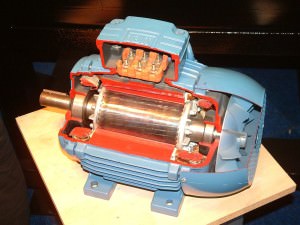
A commutator motor usually consists of a rotor (armature), stator, brushes and tachogenerator:
- Rotor- this is the rotating part, the stator is an external magnet.
- Brushes made of graphite- this is the main part of the sliding contacts, through which voltage is supplied to the rotating armature.
- Tachogenerator is a device that monitors rotation characteristics. In the event of a violation of the uniformity of movement, it adjusts the voltage supplied to the engine, thereby making it smoother.
- Stator may contain not one magnet, but, for example, 2 (2 pairs of poles). Also, instead of static magnets, electromagnet coils can be used here. Such a motor can operate on both direct and alternating current.
The ease of adjusting the speed of a commutator motor is determined by the fact that the rotation speed directly depends on the magnitude of the applied voltage.
Besides, important feature is that the rotation axis can be directly attached to rotating tools without the use of intermediate mechanisms.
If we talk about their classification, we can talk about:
- Brushed motors direct current.
- Brushed motors alternating current.
In this case, we are talking about what kind of current is used to power the electric motors.
Classification can also be made according to the principle of motor excitation. In the device of a commutator motor, power supply is supplied to both the rotor and stator of the motor (if it uses electromagnets).
The difference lies in how these connections are organized.
Here it is customary to distinguish:
- Parallel excitation.
- Consistent excitation.
- Parallel-sequential excitation.
Adjustment
Now let's talk about how you can regulate the speed of commutator motors. Due to the fact that the rotation speed of the motor simply depends on the amount of voltage supplied, any means of adjustment that are capable of performing this function are quite suitable for this.
Let's list a few of these options as examples:
- Laboratory autotransformer(LATR).
- Factory adjustment boards, used in household appliances (you can use in particular those used in mixers or vacuum cleaners).
- Buttons, used in the design of power tools.
- Household regulators lighting with smooth action.
However, all of the above methods have a very important flaw. Along with the decrease in speed, the engine power also decreases. In some cases, it can be stopped even just with your hand. In some cases, this may be acceptable, but in most cases, it is a serious obstacle.
A good option is to adjust the speed using a tachogenerator. It is usually installed at the factory. If there are deviations in the motor rotation speed, an already adjusted power supply corresponding to the required rotation speed is transmitted to the motor. If you integrate motor rotation control into this circuit, then there will be no loss of power.
How does this look constructively? The most common are rheostatic rotation control, and those made using semiconductors.
In the first case, we are talking about variable resistance with mechanical adjustment. It is connected in series to the commutator motor. The disadvantage is the additional heat generation and additional waste of battery life. With this adjustment method, there is a loss of engine rotation power. Is a cheap solution. Not applicable for sufficiently powerful motors for the reasons mentioned.
In the second case, when using semiconductors, the motor is controlled by applying certain pulses. The circuit can change the duration of such pulses, which in turn changes the rotation speed without loss of power.
How to make it yourself?
Exist various options adjustment schemes. Let us present one of them in more detail.
Here is how it works:
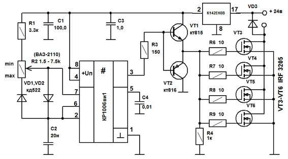
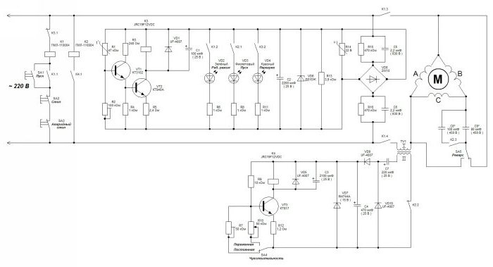
Initially, this device was developed to adjust the commutator motor in electric vehicles. We were talking about one where the supply voltage is 24 V, but this design is also applicable to other engines.
The weak point of the circuit, which was determined during testing of its operation, is poor suitability for very large values current strength. This is due to some slowdown in the operation of the transistor elements of the circuit.
It is recommended that the current be no more than 70 A. There is no current or temperature protection in this circuit, so it is recommended to build in an ammeter and monitor the current visually. The switching frequency will be 5 kHz, it is determined by capacitor C2 with a capacity of 20 nf.
As the current changes, this frequency can change between 3 kHz and 5 kHz. Variable resistor R2 is used to regulate the current. When using an electric motor at home, it is recommended to use a standard type regulator.
At the same time, it is recommended to select the value of R1 in such a way as to correctly configure the operation of the regulator. From the output of the microcircuit, the control pulse goes to a push-pull amplifier using transistors KT815 and KT816, and then goes to the transistors.
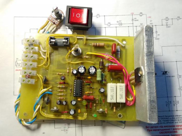
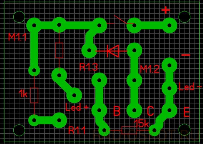
The printed circuit board has a size of 50 by 50 mm and is made of single-sided fiberglass:
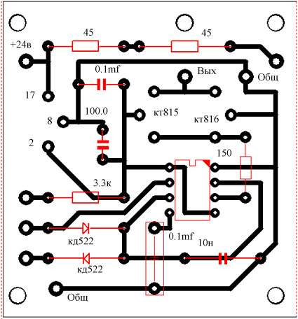
This diagram additionally shows 2 45 ohm resistors. This is done for the possible connection of a regular computer fan to cool the device. When using an electric motor as a load, it is necessary to block the circuit with a blocking (damper) diode, which in its characteristics corresponds to twice the load current and twice the supply voltage.
Operating the device in the absence of such a diode may lead to failure due to possible overheating. In this case, the diode will need to be placed on the heat sink. To do this, you can use a metal plate that has an area of 30 cm2.
Regulating switches work in such a way that the power losses on them are quite small. IN In the original design, a standard computer fan was used. To connect it, a limiting resistance of 100 Ohms and a supply voltage of 24 V were used.
The assembled device looks like this:
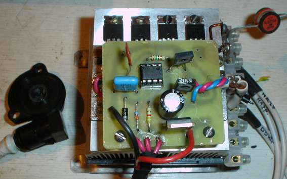
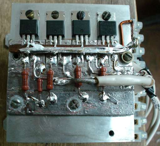
When manufacturing a power unit (in the lower figure), the wires must be connected in such a way that there is a minimum of bending of those conductors through which large currents pass. We see that the manufacture of such a device requires certain professional knowledge and skills. Perhaps in some cases it makes sense to use a purchased device.
Selection criteria and cost
In order to correctly choose the most suitable type of regulator, you need to have a good idea of what types of such devices there are:
- Various types of control. Can be a vector or scalar control system. The former are used more often, while the latter are considered more reliable.
- Regulator power must correspond to the maximum possible engine power.
- By voltage It is convenient to choose a device that has the most universal properties.
- Frequency characteristics. The regulator that suits you should be the one that best suits you high frequency, which the motor uses.
- Other characteristics. Here we are talking about the size warranty period, sizes and other characteristics.
Depending on the purpose and consumer properties, prices for regulators can vary significantly.
For the most part, they range from approximately 3.5 thousand rubles to 9 thousand:
- Speed controller KA-18 ESC, designed for 1:10 scale models. Costs 6890 rubles.
- MEGA speed controller collector (moisture-proof). Costs 3605 rubles.
- Speed controller for LaTrax 1:18 models. Its price is 5690 rubles.
The electric motor is necessary for smooth acceleration and braking. Wide Application Such devices were obtained in industry. With their help, they change the speed of conveyor belts and fan rotation. 12 Volt motors are used in control systems and automobiles. Everyone has seen the switches that change the rotation speed of the stove fan in cars. This is one of the types of regulators. It's just not designed to run smoothly. The rotation speed changes in steps.
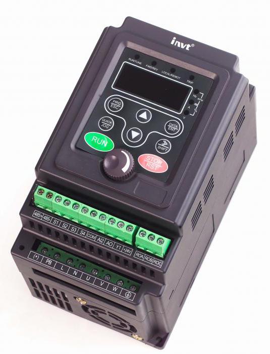
Application of frequency converters
Frequency converters are used as speed regulators and 380V. These are high-tech electronic devices that allow you to radically change the characteristics of the current (signal shape and frequency). They are based on powerful semiconductor transistors and a pulse-width modulator. All operation of the device is controlled by a microcontroller unit. The rotation speed of the engine rotor changes smoothly.
Therefore, they are used in loaded mechanisms. The slower the acceleration, the less load the conveyor or gearbox will experience. All frequencies are equipped with several degrees of protection - for current, load, voltage and others. Some models of frequency converters are powered by single-phase voltage (220 Volts) and make it three-phase. This allows you to connect asynchronous motors at home without using complex circuits. And there will be no loss of power when working with such a device.
For what purposes are regulators used?
In the case of asynchronous motors, speed controllers are needed for:
- Significant energy savings. After all, not every mechanism requires a high motor rotation speed - sometimes it can be reduced by 20-30%, and this will reduce energy costs by half.
- Protection of mechanisms and electronic circuits. Using frequency converters, you can control temperature, pressure and many other parameters. If the engine operates as a pump drive, then a pressure sensor must be installed in the container into which it pumps air or liquid. And when the maximum value is reached, the motor will simply turn off.
- Performing a soft start. There is no need to use additional electronic devices - everything can be done by changing the settings of the frequency converter.
- Reducing costs for Maintenance . With the help of such speed controllers for 220V electric motors, the risk of failure of the drive and individual mechanisms is reduced.
The circuit according to which frequency converters are built is widespread in many household appliances. Something similar can be found in uninterruptible power supplies, welding machines, voltage stabilizers, power supplies for computers, laptops, phone chargers, ignition units for backlight lamps of modern LCD TVs and monitors.
How do rotary controls work?
You can make an electric motor speed controller with your own hands, but to do this you will need to study everything technical points. Structurally, several main components can be distinguished, namely:
- Electric motor.
- Microcontroller control system and converter unit.
- Drive and mechanisms associated with it.
At the very beginning of operation, after voltage is applied to the windings, the motor rotor rotates with maximum power. It is this feature that distinguishes asynchronous machines from others. To this is added the load from the mechanism that is driven. As a result, on initial stage power and current consumption increase to the maximum.
A lot of heat is generated. Both the windings and wires overheat. Using a frequency converter will help get rid of this. If you set a soft start, then the engine will not accelerate to maximum speed (which is also regulated by the device and may not be 1500 rpm, but only 1000) not immediately, but within 10 seconds (increase 100-150 rpm every second). At the same time, the load on all mechanisms and wires will decrease significantly.
Homemade regulator
You can make your own speed controller for a 12V electric motor. This will require a multi-position switch and wirewound resistors. With the help of the latter, the supply voltage (and with it the rotation speed) changes. Similar systems can be used for asynchronous motors, but they are less efficient. Many years ago they were widely used mechanical regulators- based on gear drives or variators. But they were not very reliable. Electronic means perform much better. After all, they are not so bulky and allow you to fine-tune the drive.
To make an electric motor rotation controller you will need several electronic devices, which can either be purchased in a store or removed from old inverter devices. The VT138-600 triac shows good results in the circuits of such electronic devices. To make the adjustment, you will need to include a variable resistor in the circuit. With its help, the amplitude of the signal entering the triac changes.
Implementation of a management system
To improve the parameters of even the most simple device, you will need to include microcontroller control in the electric motor speed controller circuit. To do this, you need to select a processor with a suitable number of inputs and outputs - for connecting sensors, buttons, electronic keys. For experiments, you can use the AtMega128 microcontroller - the most popular and easiest to use. You can find many schemes using this controller in the public domain. Finding them yourself and applying them in practice is not difficult. In order for it to work correctly, you will need to write an algorithm into it - responses to certain actions. For example, when the temperature reaches 60 degrees (measured on the radiator of the device), the power should be turned off.
Finally
If you decide not to make a device yourself, but to purchase a ready-made one, then pay attention to the main parameters, such as power, type of control system, operating voltage, frequencies. It is advisable to calculate the characteristics of the mechanism in which it is planned to use the motor voltage regulator. And don’t forget to compare it with the parameters of the frequency converter.
Hello everyone, probably many radio amateurs, like me, have more than one hobby, but several. In addition to designing electronic devices, I do photography, video shooting with a DSLR camera, and video editing. As a videographer, I needed a slider for video shooting, and first I’ll briefly explain what it is. The photo below shows the factory slider.
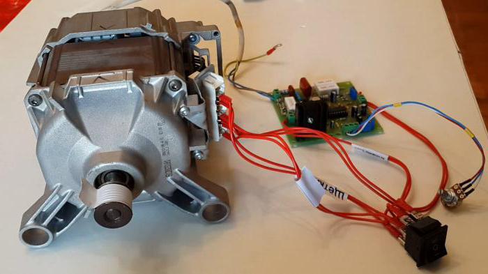
The slider is designed for video shooting on cameras and video cameras. It is analogous to the rail system used in wide-format cinema. With its help, a smooth movement of the camera around the object being photographed is created. Another very powerful effect that can be used when working with a slider is the ability to move closer or further from the subject. The next photo shows the engine that was chosen to make the slider.
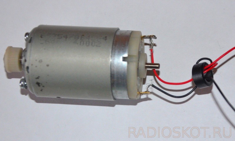
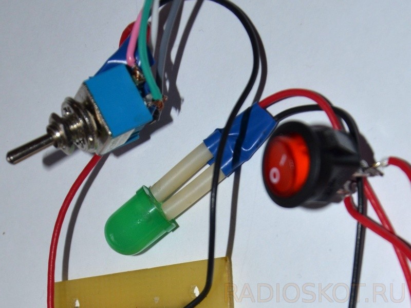
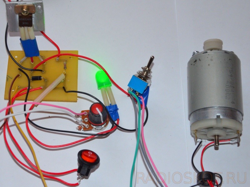
The slider is driven by a 12-volt DC motor. A diagram of a regulator for the motor that moves the slider carriage was found on the Internet. The next photo shows the power indicator on the LED, the toggle switch that controls the reverse and the power switch.
When operating such a device, it is important that there is smooth speed control, plus easy inclusion of engine reverse. The speed of rotation of the motor shaft, in the case of using our regulator, is smoothly adjusted by rotating the handle variable resistor at 5 kOhm. Perhaps I am not the only one of the users of this site who is interested in photography, and someone else will want to replicate this device; those who wish can download an archive with a diagram and printed circuit board regulator The following figure shows circuit diagram engine regulator:
Regulator circuit
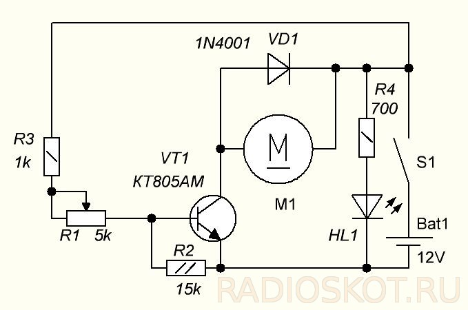
The circuit is very simple and can be easily assembled even by novice radio amateurs. Among the advantages of assembling this device, I can name its low cost and the ability to customize it to meet your needs. The figure shows the controller's printed circuit board:
But the scope of application of this regulator is not limited to sliders alone; it can easily be used as a speed regulator, for example, a machine drill, a homemade Dremel powered by 12 volts, or a computer cooler, for example, with dimensions of 80 x 80 or 120 x 120 mm. I also developed a scheme for reversing the engine, or in other words, quickly changing the rotation of the shaft in the other direction. To do this, I used a six-pin toggle switch with 2 positions. The following figure shows its connection diagram:
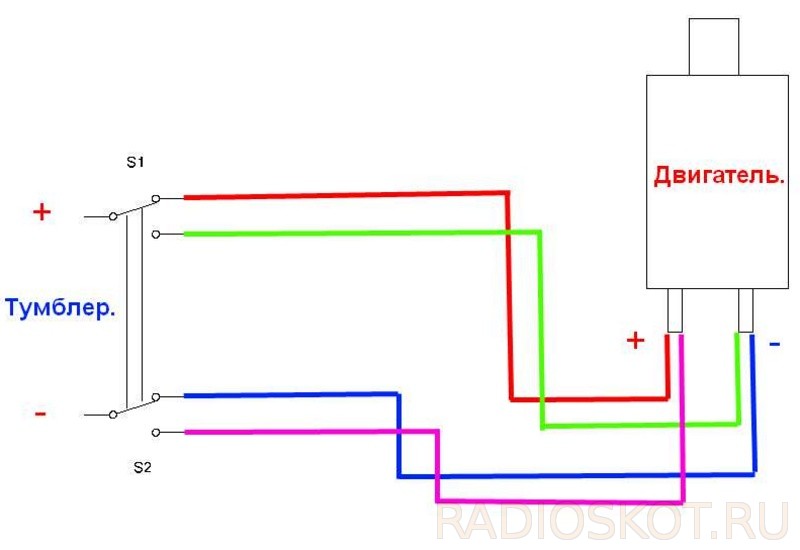
The middle contacts of the toggle switch, marked (+) and (-), are connected to the contacts on the board marked M1.1 and M1.2, the polarity does not matter. Everyone knows that computer coolers, when the supply voltage and, accordingly, the speed are reduced, make much less noise during operation. In the next photo, the KT805AM transistor is on the radiator:
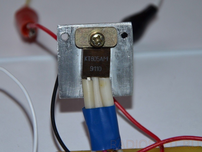
Almost any medium to large transistor can be used in the circuit power n-p-n structures. The diode can also be replaced with analogues suitable for current, for example 1N4001, 1N4007 and others. The motor terminals are shunted by a diode in reverse connection; this was done to protect the transistor during switching on and off moments of the circuit, since our motor has an inductive load. Also, the circuit provides an indication that the slider is turned on on an LED connected in series with a resistor.
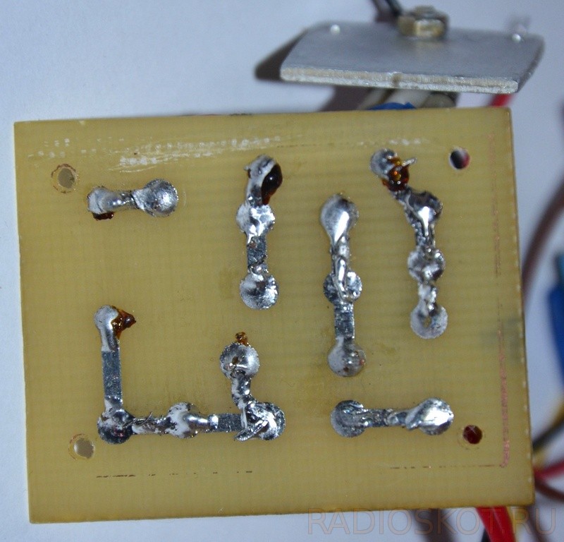
When using an engine of greater power than shown in the photo, the transistor must be attached to the radiator to improve cooling. A photo of the resulting board is shown below:
Discuss the article ENGINE SPEED CONTROL WITH REVERSE


