An electric soldering iron is available in every household. home handyman. No repairs can be done without it. electrical devices, nor when connecting various small metal parts. But sometimes the soldering iron can fail. If this happens, then you shouldn’t always rush to buy a new one. Of course, not always, but you can repair a soldering iron yourself, without resorting to the services of specialists for a fairly substantial fee. As a rule, repairing an electric household soldering iron consists of replacing the heating element, which serves to heat the tip of our device. In this article we will focus on this breakdown in more detail.
For example, we will take an electric soldering iron with a power of 40 Watt, designed for a voltage of 220 Volts.
For repair work we will need following materials and tools:
- ceramic resistance PEV-10;
- asbestos thread;
- pliers (pliers);
- hacksaw for metal;
- screwdriver;
- sharp knife.
Next, we will break down the entire repair process, i.e. replacing the heating element, step by step. 
Step one. To replace a failed one, we take a ceramic resistor of the PEV-10 type with a nominal resistance of 1.0 to 1.5 kOhm. The hole located in the center of our resistor has a diameter through which a soldering iron tip can be easily inserted, without any additional adjustment required.
Step number two. Remove the old burnt out heating element. On the metal body protecting the heating element, from the side of the longitudinal seam, we make a transverse cut, approximately to the middle. We retreat from the edge by 4 cm. Then we unfold the sawn sides of the tube and cut off the corners of the resulting nest. This is necessary in order to avoid electrical contact of the metal case with the resistance terminals.
Use an adsense clicker on your websites and blogs or on YouTube
Step three. We insert the PEV-10 resistance, which will serve as a heating element in our soldering iron, into the socket we made. We bend the metal petals of the body, surrounding them with the socket. We secure the resistance in the socket using a clamp.
Fourth step. After carrying out technical measures, we move on to electrical ones. We need to connect to the installed heating element, i.e. Apply voltage to PEV-10. To do this, we clear the wire strands of insulation at a distance of 1.5 - 2 cm from the edge.
Step five. We tightly wrap the loose ends of the wire along the entire length with asbestos thread - turn to turn. We pull the thread-insulated ends of the wire through the handle channels and connect them to the terminals of the new heating element. To make installation easier, bend the resistor leg, insert the pre-stripped tip of the wire inside the bent part and crimp it with pliers.
Step number six. We insulate the heater leads with the same asbestos thread, tightly winding them turn to turn. The wires must be laid so that they do not come into contact with the housing. We re-wrap both conductors with thread, fastening them together. Assembling the soldering iron handle. Now our repaired soldering iron is ready for use again.
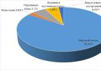
During repairs or self-production electric soldering iron or any other heating device you have to wind the heating winding from nichrome wire. The initial data for calculating and selecting wire is the winding resistance of a soldering iron or heating device, which is determined based on its power and supply voltage. You can calculate what the winding resistance of a soldering iron or heating device should be using the table.
Knowing the supply voltage and measuring resistance any heating electrical appliance, for example a soldering iron, or electric iron, you can find out the power consumed by this household electrical appliance b. For example, the resistance of a 1.5 kW electric kettle will be 32.2 Ohms.
| Table for determining the resistance of a nichrome spiral depending on power and supply voltage electrical appliances, Ohm | |||||
|---|---|---|---|---|---|
| Power consumption soldering iron, W | Soldering iron supply voltage, V | ||||
| 12 | 24 | 36 | 127 | 220 | |
| 12 | 12 | 48,0 | 108 | 1344 | 4033 |
| 24 | 6,0 | 24,0 | 54 | 672 | 2016 |
| 36 | 4,0 | 16,0 | 36 | 448 | 1344 |
| 42 | 3,4 | 13,7 | 31 | 384 | 1152 |
| 60 | 2,4 | 9,6 | 22 | 269 | 806 |
| 75 | 1.9 | 7.7 | 17 | 215 | 645 |
| 100 | 1,4 | 5,7 | 13 | 161 | 484 |
| 150 | 0,96 | 3,84 | 8,6 | 107 | 332 |
| 200 | 0,72 | 2,88 | 6,5 | 80,6 | 242 |
| 300 | 0,48 | 1,92 | 4,3 | 53,8 | 161 |
| 400 | 0,36 | 1,44 | 3,2 | 40,3 | 121 |
| 500 | 0,29 | 1,15 | 2,6 | 32,3 | 96,8 |
| 700 | 0,21 | 0,83 | 1,85 | 23,0 | 69,1 |
| 900 | 0,16 | 0,64 | 1,44 | 17,9 | 53,8 |
| 1000 | 0,14 | 0,57 | 1,30 | 16,1 | 48,4 |
| 1500 | 0,10 | 0,38 | 0,86 | 10,8 | 32,3 |
| 2000 | 0,07 | 0,29 | 0,65 | 8,06 | 24,2 |
| 2500 | 0,06 | 0,23 | 0,52 | 6,45 | 19,4 |
| 3000 | 0,05 | 0,19 | 0,43 | 5,38 | 16,1 |
Let's look at an example of how to use the table. Let's say you need to rewind a 60 W soldering iron designed for a supply voltage of 220 V. In the leftmost column of the table, select 60 W. From the top horizontal line, select 220 V. As a result of the calculation, it turns out that the resistance of the soldering iron winding, regardless of the winding material, should be equal to 806 Ohms.
If you needed to make a soldering iron from a 60 W soldering iron, designed for a voltage of 220 V, for power supply from a 36 V network, then the resistance of the new winding should already be equal to 22 Ohms. You can independently calculate the winding resistance of any electric heating device using an online calculator.
After determining the required resistance value of the soldering iron winding, the appropriate diameter of the nichrome wire is selected from the table below, based on the geometric dimensions of the winding. Nichrome wire is a chromium-nickel alloy that can withstand heating temperatures up to 1000˚C and is marked X20N80. This means that the alloy contains 20% chromium and 80% nickel.
To wind a soldering iron spiral with a resistance of 806 Ohms from the example above, you will need 5.75 meters of nichrome wire with a diameter of 0.1 mm (you need to divide 806 by 140), or 25.4 m of wire with a diameter of 0.2 mm, and so on.
When winding a soldering iron spiral, the turns are laid close to each other. When heated red-hot, the surface of the nichrome wire oxidizes and forms an insulating surface. If the entire length of the wire does not fit on the sleeve in one layer, then the wound layer is covered with mica and a second one is wound.
For electrical and thermal insulation of heating element windings the best materials is mica, fiberglass cloth and asbestos. Asbestos has an interesting property: it can be soaked with water and it becomes soft, allows you to give it any shape, and after drying it has sufficient mechanical strength. When insulating the winding of a soldering iron with wet asbestos, it must be taken into account that wet asbestos conducts electric current well and it will be possible to turn on the soldering iron to the electrical network only after completely dry asbestos.
An electric soldering iron is a hand-held heating device for fixing metal parts using solder - an alloy heated to a liquid state and having a melting point lower than that of the workpieces being fastened.
Design
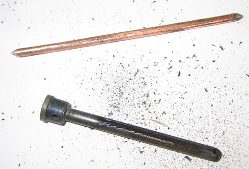
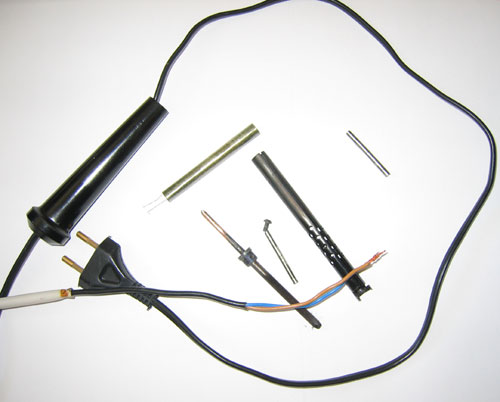
The operation of electric soldering irons requires knowledge of their designs in order to quickly identify damage and repair the device at any unexpected moment. It consists of:
- a copper rod wrapped in insulating material and placed in a steel tube;
- heater;
- tips for directly connecting metal parts with solder;
- handle holder;
- cord with plug.
The copper rod is an effective conductor of heat from the heater (nichrome spiral) to the tip. The spiral is wound onto a steel tube, which is wrapped in mica or fiberglass. Next, the nichrome winding is covered with an insulator (preferably asbestos), which prevents heat loss and short circuits.

To reduce heating in the area of connection with the conductors of the power cord, the ends of the spiral are bent in half, and the contact point is supplemented with a crimping aluminum plate. Electrical insulation is ensured by insulating tubes placed at the twisting point.
The rod and heater are placed in the body of the soldering iron, onto which a wooden or thermoplastic handle with an internal channel for the power cord is attached.
Operation
The operating principle of a soldering tool is based on the conversion of electrical energy into thermal energy, which heats the tip through heating the coil and rod. The temperature in the soldering zone reaches 400-4500C. The resulting viscous-liquid mixture penetrates into cavities and irregularities between parts. After cooling, the metals will be securely connected.
Additional Information. The electrical circuit usually contains an AC to DC converter.
Power
The operating power of the soldering iron is selected from 12 to 3000 W and determines its technical capabilities. Soldering small parts performed by a 12 W device. This condition must be met, since a powerful soldering iron, due to the size of the tip, will not be able to reach the contact points of tiny radio elements. In addition, the high power of the device causes unacceptable overheating of the circuit parts.

For powerful radio components, thick wires and small elements, 40 and 60 W soldering irons are required. If work is performed on large equipment, then the soldering tool is selected for 100 W or higher. If the power of the device is insufficient, the soldering will be weak and have a large number of voids.
Voltage
To comply with safety precautions, the soldering iron is selected according to the mains voltage from 12 to 220 V (5 values in total). Thus, work in passenger vehicles can be carried out with a soldering tool at 12 V, in trucks - 24, in air - 27, in a damp room with mandatory grounding of electrical equipment - 36 V.
It is not easy to convert a 12 V tool to 220 V - you will have to wind a thin spiral with a large number of layers, which creates certain inconveniences when working with small parts.
Note! If the power of the network and the soldering iron match, you can work from alternating and direct voltage. This possibility is due to the nichrome material of the heater.
Basically, the voltage in soldering tools is 220 V. To prevent electric shock in high humidity or dusty areas, use a tool voltage of no more than 42 V.
Kinds
The most popular types of soldering irons can be classified into two categories: heating features and design types.
According to the heating principle, soldering devices are distinguished:
- nichrome;
- ceramic;
- induction;
- pulsed.
Nichrome
The most common soldering iron device is with a spiral heater made of nichrome, through which direct mains current or alternating current from the mains and transformer can pass. This tool is affordable and shock-resistant. Suitable for infrequent use.
Ceramic
In this type of soldering iron, the heater is a ceramic rod through which thermal energy from live contacts. Among the advantages noted: long term services at correct operation, fairly fast heating, presence of a temperature and power control system, compactness.

Disadvantages include: fragility of the ceramic rod, use of only the original tip, high cost, risk of purchasing a nichrome fake.
Induction
The inductor coil, as the main working part of the soldering iron, creates a magnetic field and heats the core. Heat is transferred to the tip, which is maintained at a temperature thanks to the ferromagnetic coating.
Each metal and part requires its own heating, so the tip must be selected individually.
Pulse
The pulse soldering iron circuit contains: a frequency converter, transformer high frequency and sting. An electrical impulse occurs with increasing frequency of the mains voltage, which after a short time decreases to the required value.
The tip is connected using clamps (current collectors) to the secondary transformer winding. Thanks to this, when you press and hold the start button, the end part of the tool instantly warms up.

Soldering irons of this type are designed for short-term soldering of parts of various sizes.
According to design differences, soldering devices are divided into:
- rod - the handle-holder turns into a straight rod with a sting;
- pistol type - the handle and the metal part are perpendicular to each other;
- soldering stations are complex devices with a built-in electronic control unit; according to operating technology, they are divided into infrared, hot-air, and digital.
There are models of soldering irons for children's technical modeling - low-power with wooden handle. Compact USB devices operate from a car cigarette lighter, and hammer soldering irons are equipped with a thick tip for large parts. Battery and gas tools are self-contained devices and operate from a battery and gas canister, respectively.
Soldering tools may have tips various configurations(wedge-shaped, cone-shaped, chamfered, needle-shaped), made of copper or additionally with nickel plating. The handle is made of material with low thermal conductivity: wood, ebonite, textolite.
Note! Before work, you must familiarize yourself with the rules for operating and repairing the soldering iron.
terms of Use
Soldering iron repair is unlikely to be required if you follow necessary rules operation:
- ensure safety precautions at the workplace in accordance with the product instructions;
- take into account the value of the mains voltage;
- in rooms with high humidity, use a 36 V device (no more), first grounding it;
- The heater and cord must be free from mechanical loads during operation;
- do not touch the cord with a hot tip;
- do not overheat the soldering iron coil;
- select the heating mode using the power regulator.
Important! Correct selection power parameters does not guarantee the quality of soldering.
Causes of damage
Most common following reasons failure of the soldering tool:
- damage to the plug or cord;
- network failure;
- violation of work contacts;
- heater failure.
How to repair
To prevent sudden damage to the instrument from causing inconvenience, every specialist or radio amateur must confidently wield a soldering iron and be able to repair it, especially since it is not difficult. It is necessary to have a conventional ampere-voltmeter that diagnoses the type of malfunction.

Replacing the heater with a new one
If the heating element loses its functionality, do the following:
- determine the winding resistance based on the power of the device and the network voltage;
- select the diameter of the nichrome wire according to the resistance of 1 meter;
- wind the spiral, laying the turns without gaps, placing a layer of mica between the rows;
- in order to retain heat and prevent short circuits, the winding is covered with fiberglass, instead of which mica or asbestos can be used; the latter has the advantage of creating the required shape and acquiring strength after drying.
Note! After applying the asbestos insulating layer, you need to wait for it to dry and only then turn on the device to the network.
Replacing the heater with a resistor
Instead of a heating element, you can successfully use a PEV-10 resistor. To repair a soldering iron with your own hands, you will need pliers, a well-sharpened knife, and asbestos thread. To replace the heater, you must:
- disassemble the soldering tool;
- remove the used heater;
- place the resistor in the vacant space;
- remove 1.5 cm of insulating coating from the power cord, connect the power wires to the resistor through the holder channel; make sure that the laid wires do not touch the housing; insulate the terminals with asbestos thread;
- assemble the tool and make sure it works.
If the power cord is damaged, it should be replaced. A faulty power cord plug must also be replaced. In this case, the broken fork (usually a solid one) is cut off and a collapsible one is installed instead.
Broken contact of the heater with the power cord can be easily eliminated. To do this, you need to disassemble the soldering iron and restore the connection of the contacts.
If you work with the soldering iron carefully, it will not require repair for a long time. If damage does occur, it is quite simple to fix it: you need to know the circuit diagram of the device (it is elementary), the basic rules of electrical engineering and safety.
Video
Have you purchased a soldering iron, but are not satisfied with the quality of its work? Then you will find in this article material on how to repair a soldering iron if you do not want to take it to a workshop, but decide to do it yourself. In the presented video tutorial we're talking about about a cheap Chinese device in which some parts need to be replaced.
Unusual soldering irons are sold cheaply in a Chinese online store.
First, look at what you need to remake a soldering iron:
- soldering iron;
- thick copper wire;
- screwdriver;
- drill;
- the wire;
- wire cutters;
- electrical tape;
- fork;
- flux;
- tin;
- metal sponge.
The first thing we will pay attention to is the ineffective soldering iron tip. replace it with copper wire required diameter. Let's take out the old tip and make it out of copper to the same size (thickness and length).
All that remains is to tin the tip and you can solder with the normal soldering apparatus you have modified.
Notes Another disease of Chinese soldering irons is severe overheating during operation. It can be eliminated by inserting into the gap one of the wires a diode with an operating voltage of at least 300 volts (it can be mounted in a power plug; the polarity of the connection does not matter). In order for the soldering iron tip to burn less, before work it must be forged in a cold state with a small hammer; in this case, the copper becomes denser and does not burn so quickly.
DISASSEMBLY AND REWINDING THE SOLDERING IRON
If you, a fellow hobbyist, have already “outgrown” soldering iron with voltage regulator. but I haven’t yet grown up in my ambitions to become a professional soldering station. then this might be interesting. The ability to change the supply voltage of a soldering iron designed for 220 V, among other things, allows you to return to operation an already burnt-out one. And use it in the future, for example, with a switching power supply from an imported TV, which at the output gives exactly half of the network one. Bringing these two products together results in an intermediate option between a soldering iron with a regulator and a full-fledged soldering station. Any radio amateur can do this. I’ll show you how to do this using the example of changing the supply voltage of a soldering iron. made in China, which was not credible for use without modification.
Disassembling the soldering iron

To disassemble the soldering iron, it was necessary to completely unscrew two screws connecting the protective casing to the heating element and holding the tip, and three self-tapping screws securing the working part to the handle. Remove the insulation from the wires and unscrew the connecting twists.

Mica with soldering iron spiral
There is a heating element inside the protective casing. That's what they have to do. It is necessary to change the amount of wound nichrome wire - change the resistance of the heating element. Now it is 1800 Ohms, 400 Ohms are needed. Why exactly so much? Currently working with a UPS, the soldering iron has a resistance of 347 Ohms, its power is from 19 to 28 W, there is a desire to make the second one less powerful, so I added Ohms.
Soldering iron rewind

Winding a soldering iron tip
The tip is reinserted into the heater, clamped with screws and into the drill chuck. If you disassemble and unwind excess nichrome while holding the heating element in your hands, then everything will be much more complicated. The tie wire is removed.

The released fiberglass and mica wrappers are removed. There is a slot in the mica on the side of the tip into which a conductor is inserted, running from the nichrome to the power cable - therefore, the weakened mica wrapper is removed from it rather than unwound. Mica is a very fragile material. The end of the nichrome wire wound to the conductor is disconnected. Its thickness is just over 4 microns.

Nichrome must be wound onto something round, perfect option- spool for thread. I unscrewed it, rewinded it, and so on until the end. There is no need to disconnect the second end of the nichrome wire.

Soldering iron wire resistance
Now you need to wind a length of 400 Ohms, and in centimeters it will be approximately 70 (the total length of nichrome wire 300 cm is 1800 Ohms, hence 400 Ohms will be 66.66 cm). At a length of 70 cm, a latch (clothespin) is placed and in the hanging position of the coil, slightly guiding with your fingers, winding is carried out at intervals ensuring its termination at the first conductor. The number of attempts is not limited, the main thing is not to tear the nichrome. At the end of winding, a control resistance measurement is required.

As soon as I managed to reel required quantities nichrome, cut the wire with an allowance of 1 - 2 cm and wind it to the conductor. We put on the mica winding, passing the conductor into the slot in it and press it against it (naturally on top of it).

We install a fiberglass winding on top and, compacting it by pressing, wind the binding wire. A heating element designed for power supply voltage of 85 - 106 V is assembled.
Soldering iron assembly

Since the working part was previously attached to the handle with incomprehensibly clumsy and short screws, they had to be replaced. To do this, holes for new screws were deepened in the attachment points on the handle.

Before connecting the power cable with the conductors going to the nichrome heater, a plastic clamp was installed and adjusted on it.

The casing of the heating element ends with a kind of cooling radiator, through holes in it and is attached to the handle. To increase the cooling effect, the gap between it and the handle was increased using metal washers.

Soldering iron current consumption 190 mA
The UPS with which the soldering iron will work at the output under load gives from 85 to 106 V. Current consumption is 190 mA, this is at the minimum voltage. Power 16 W.

Soldering iron current consumption 240 mA
At maximum voltage, current consumption is 260 mA. Power 26 W. The desired has been received.

Finally, a test for heating duration. Up to 257 degrees in 2 minutes 20 seconds. An excellent result, if you take into account that from a 225 V network it heated up to 250 degrees in 5 and a half minutes.

Table. Dependence of the resistance of the heating element on the power and voltage of the soldering iron
And here is a table that will help you navigate the required resistance of the heating element, depending on the desired power and the available supply voltage. Author: Babay iz Barnaula.
Many people are guilty of fetishism. Everyone has their own object of adoration. I would venture to guess that for radio amateurs this is most often a soldering iron. I had one like that, until I decided to make an improvement - I put a diode in the break in the wire and a toggle switch to it. Well, everyone knows this rationalization and has been for a long time. Convenient, liked it. But the soldering iron burned out. In just a month. It's clear that it's a coincidence. I repaired it - I fastened (crimped) the ends at the burnout site with a piece of copper plate. And a month later again. The second plate did not fit in the heating element. A year has passed. And now, extracting from the board of an imported TV pulse block power supply, I figured out how to give a second life to a faithful partner - if there is not a sufficient length of whole nichrome wire (where can I get it with a diameter of 0.08 mm?) to wind the heating element at a voltage of 220V, then this can be done at a lower voltage, for example 110V, from the available “scraps9raquo; (you need less nichrome).

To begin with, I made measurements and calculations. I measured the resistance of an existing whole piece of nichrome - 367 Ohms. The output voltage of the power supply, took the value of 110V, divided by 367 Ohms and got the required current - 0.3 A, multiplying it by 110V, I found out the estimated possible power of the soldering iron - 33W. Quite enough. The existing mandrel with a dielectric (mica) wound on top was placed in a cartridge hand drill, tied nichrome at one end to a conductor wire, and wound the other on an improvised bobbin, attaching clothespins for weight.


It's not ideal, though. The main thing here is that the turns do not touch each other. The second end of nichrome to the second wire - the conductor. On top of the nichrome there is again a dielectric, of course you need mica, but there wasn’t any - in the photo there is an asbestos cord.

The conductors (wires) are bent in the desired direction, the farthest one is pressed against the asbestos. The contact between conductors - wires must be EXCLUDED. On top is again a dielectric - mica.

Then everything is simple: we pass the wire coming from the plug through the handle of the soldering iron and the casing, and connect its cores by twisting with the conductors in contact with the nichrome, having previously put on the last insulators that were on them before disassembly. We insert everything into the casing.

Handle casing. The tip is inside the heating element mandrel.

Now be sure to “call 9raquo; the pins of the power plug relative to the casing and soldering iron tip! THERE SHOULD BE NO CONTACT.

“Chassis9raquo; the tests were successful. The fact that you shouldn’t plug this soldering iron into a 220-volt outlet is, of course, clear to everyone. And smooth temperature control, if necessary, is achieved according to this scheme. With best wishes, Babay. Russia, Barnaul.
Repairing a burnt soldering iron (for soldering parts), replacing the heating element with your own hands.
Topic: what to do if a soldering iron burns out, how to restore it yourself.
 Sometimes the soldering iron you use to solder various schemes, parts, wires suddenly stop working, it does not heat up. In most cases, it may be a simple break in the wire that powers the electric soldering iron itself. The most vulnerable point of the wire is the area where it is frequently bent. For a soldering iron (and not only for it) this is the place where the wire enters the soldering iron itself. You just need to disassemble it and ring the wires coming from the plug. If the wire does not ring, then simply cut off a small piece (about 15 cm long) from the entrance to the soldering iron. Call again. If there is still no contact, then cut the same piece from the plug side. Well, as a last resort, just install a new wire.
But not in all cases, the reason why an electric soldering iron does not work is a break in the wire powering it. Sometimes the heating element itself burns out inside the soldering iron. There are two ways to go here. You can try to rewind the heating coil yourself. This is a fairly simple task if you have something to rewind and if the soldering iron was designed for a voltage no higher than 36 volts. For a soldering iron supply voltage of 220 volts, rewinding the spiral will be much more difficult. A thin and long wire must be carefully wound (so that the turns do not have direct contact) around the base of the heater. For a beginner, this is difficult and time-consuming.
 You can go another way. Repairing a burnt soldering iron involves replacing the entire heating element. For example, when the problem of a burnt soldering iron affected me, I went to the aliexpress website, typed in “soldering iron heater” into the search, and then chose the most suitable option(by size, by the power I need and supply voltage). The cost of this heating element was quite low (when compared with buying a new electric soldering iron). Then I placed an order, paid, delivery took about 2 weeks.
Installing a new heating element on a burnt-out soldering iron was not difficult. It fit normally into the base of the soldering iron. Except that the old tip was slightly larger in size than the hole that was on the new heater. I just took a piece of copper wire required length and diameter. One end of it (the one that will be soldered) was ground off at an angle. The heating element is fixed with one short screw on one side of the base of the soldering iron. The tip itself is fixed with another screw (slightly longer than the first) on the other side of the base.
The outgoing wires from the heating element were twisted with the wires of the power cord. Having previously put on them small pieces of polyvinyl chloride tube, which has heat-resistant properties. These pieces of tubes act as electrical insulators, which prevent short circuits from occurring at the junction of the wires. Conventional insulation in the form of electrical tape or shrink heat tube will not work, as it will simply collapse when the soldering iron heats up. You can also use fabric or fiberglass tape. That’s basically all the work involved in repairing a burnt-out soldering iron.
P.S. If we talk about what will be cheaper - repair or purchase of a new soldering iron, then repair by replacing a burnt heating element will still cost much less. Whether you can replace it yourself or not is another matter. When purchasing, pay attention to the dimensions of the new heating element, as even a small discrepancy may lead to additional adjustment steps. In addition, make sure that the power and voltage correspond to the values that you need.
Construction and repair of an electric soldering iron
An electric soldering iron is hand tool, intended for fastening parts together by means of soft solders. by heating the solder to a liquid state and filling the gap between the parts being soldered with it.

Electric soldering irons are produced designed for mains voltages of 12, 24, 36, 42 and 220 V, and there are reasons for this. The main thing is human safety, the second is the network voltage at the place where the soldering work is performed. In production where all equipment is grounded and there is high humidity, it is allowed to use soldering irons with a voltage of no more than 36 V, and the body of the soldering iron must be grounded. The motorcycle's on-board network has voltage direct current 6 V, passenger car- 12 V, cargo - 24 V. In aviation, they use a network with a frequency of 400 Hz and a voltage of 27 V. There are also design limitations, for example, a 12 W soldering iron is difficult to make for a supply voltage of 220 V, since the spiral will need to be wound from a very thin wire and Therefore, if you wind many layers, the soldering iron will turn out to be large, not convenient for small work. Since the soldering iron winding is wound from nichrome wire, it can be powered with either alternating or direct voltage. The main thing is that the supply voltage matches the voltage for which the soldering iron is designed.
Electric soldering irons come in power ratings of 12, 20, 40, 60, 100 W and more. And this is also no coincidence. In order for the solder to spread well over the surfaces of the parts being soldered during soldering, they need to be heated to a temperature slightly higher than the melting point of the solder. Upon contact with a part, heat is transferred from the tip to the part and the temperature of the tip drops. If the diameter of the soldering iron tip is not sufficient or the power of the heating element is small, then, having given off heat, the tip will not be able to heat up to the set temperature, and soldering will be impossible. At best, the result will be loose and not strong soldering. More powerful soldering iron You can solder small parts, but there is a problem of inaccessibility to the soldering point. How, for example, to solder in printed circuit board a microcircuit with a leg pitch of 1.25 mm with a soldering iron tip measuring 5 mm? True, there is a way out: several turns of copper wire with a diameter of 1 mm are wound around such a sting and the end of this wire is soldered. But the bulkiness of the soldering iron makes the work practically impossible. There is one more limitation. At high power, the soldering iron will quickly heat up the element, and many radio components do not allow heating above 70˚C and therefore the permissible soldering time is no more than 3 seconds. These are diodes, transistors, microcircuits.
Soldering iron device
The soldering iron is a red copper rod, which is heated by a nichrome spiral to the melting temperature of the solder. The soldering iron rod is made of copper due to its high thermal conductivity. After all, when soldering, you need to quickly transfer heat from the soldering iron tip from the heating element. The end of the rod is wedge-shaped, is the working part of the soldering iron and is called the tip. The rod is inserted into a steel tube wrapped in mica or fiberglass. A nichrome wire is wound around the mica, which serves as a heating element.

A layer of mica or asbestos is wound over the nichrome, which serves to reduce heat loss and electrically insulate the nichrome spiral from the metal body of the soldering iron.

The ends of the nichrome spiral are connected to copper conductors electrical cord with a fork at the end. To ensure the reliability of this connection, the ends of the nichrome spiral are bent and folded in half, which reduces heating at the junction with copper wire. In addition, the connection is crimped with a metal plate; it is best to make the crimp from an aluminum plate, which has high thermal conductivity and will more effectively remove heat from the joint. For electrical insulation, tubes made of heat-resistant insulating material, fiberglass or mica are placed at the junction.

The copper rod and nichrome spiral are closed with a metal case consisting of two halves or a solid tube, as in the photo. The body of the soldering iron is fixed on the tube with cap rings. To protect a person’s hand from burns, a handle made of a material that does not transmit heat well, wood or heat-resistant plastic, is attached to the tube.

When inserting the soldering iron plug into the outlet electricity goes to a nichrome heating element, which heats up and transfers heat to the copper rod. The soldering iron is ready for soldering.
Low-power transistors, diodes, resistors, capacitors, microcircuits and thin wires are soldered with a 12 W soldering iron. Soldering irons 40 and 60 W are used for soldering powerful and large-sized radio components, thick wires and small parts. To solder large parts, for example, heat exchangers of a geyser, you will need a soldering iron with a power of one hundred or more watts.
Electrical circuit of a soldering iron
As you can see in the drawing electrical diagram The soldering iron is very simple, and consists of only three elements: a plug, a flexible electrical wire and a nichrome spiral.

As can be seen from the diagram, the soldering iron does not have the ability to adjust the heating temperature of the tip. And even if the power of the soldering iron is chosen correctly, it is still not a fact that the temperature of the tip will be required for soldering, since the length of the tip decreases over time due to its constant refilling; solders also have different melting temperatures. Therefore, to maintain optimal temperature soldering iron tips have to be connected through thyristor power regulators with manual adjustment and automatic maintenance the set temperature of the soldering iron tip.
Calculation and repair of the heating winding of a soldering iron
When repairing or making your own electric soldering iron or any other heating device, you have to wind a heating winding made of nichrome wire. The initial data for calculating and selecting wire is the winding resistance of a soldering iron or heating device, which is determined based on its power and supply voltage. You can calculate what the winding resistance of a soldering iron or heating device should be using the table.
Knowing the supply voltage and measuring the resistance of any heating electrical appliance, such as a soldering iron or electric kettle. electric heater or electric iron. You can find out the power consumed by this household appliance. For example, the resistance of a 1.5 kW electric kettle will be 32.2 Ohms.
Table for determining the resistance of a nichrome spiral depending on the power and supply voltage of electrical devices, Ohm
Power consumption
soldering iron, W
Let's look at an example of how to use the table. Let's say you need to rewind a 60 W soldering iron designed for a supply voltage of 220 V. In the leftmost column of the table, select 60 W. From the top horizontal line, select 220 V. As a result of the calculation, it turns out that the resistance of the soldering iron winding, regardless of the winding material, should be equal to 806 Ohms.
If you needed to make a soldering iron from a 60 W soldering iron, designed for a voltage of 220 V, for power supply from a 36 V network, then the resistance of the new winding should already be equal to 22 Ohms. You can independently calculate the winding resistance of any electric heating device using an online calculator.
Online calculator for calculating the resistance value based on power consumption
Supply voltage, V:
After determining the required resistance value of the soldering iron winding, the appropriate diameter of the nichrome wire is selected from the table below, based on the geometric dimensions of the winding. Nichrome wire is a chromium-nickel alloy that can withstand heating temperatures up to 1000˚C and is marked X20N80. This means that the alloy contains 20% chromium and 80% nickel.
Table of dependence of linear resistance (one meter) of nichrome wire on its diameter
Diameter of nichrome wire, mm
To wind a soldering iron spiral with a resistance of 806 Ohms from the example above, you will need 5.75 meters of nichrome wire with a diameter of 0.1 mm (you need to divide 806 by 140), or 25.4 m of wire with a diameter of 0.2 mm, and so on.
When winding a soldering iron spiral, the turns are laid close to each other. When heated red-hot, the surface of the nichrome wire oxidizes and forms an insulating surface. If the entire length of the wire does not fit on the sleeve in one layer, then the wound layer is covered with mica and a second one is wound.
For electrical and thermal insulation of the heating element winding, the best materials are mica, fiberglass cloth and asbestos. Asbestos has an interesting property: it can be soaked with water and it becomes soft, allows you to give it any shape, and after drying it has sufficient mechanical strength. When insulating the winding of a soldering iron with wet asbestos, it is necessary to take into account that wet asbestos conducts electric current well and it will be possible to turn on the soldering iron into the electrical network only after the asbestos has completely dried.
Let me remind you that we have in our hands a soldering iron with a torn off power cord. Tasks for the next half hour:
A) get acquainted with the internal structure of the hero of the review;
b) if possible, bring him back to life.
The first thing we do is remove the handle made of heat-resistant plastic. What remains in your hands is – let’s call it that – a “casing”, in which all the patient’s insides are actually located.
We unscrew the only bolt - two or three turns allow you to fix or release the rod, which actually does the soldering, and its complete separation from the thread allows you to remove the “cartridge” for the rod.
On the other side of the “casing” we bend two antennae and first carefully take out two thin tubes about 4 cm long, metallic color, and behind them - the heating element itself - a tube of the same type with a larger diameter and length, in which a spiral of metal with a high resistivity(most likely nichrome).
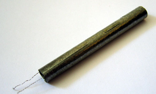

As you can see, the contacts of our spiral remained intact - great news. To ensure the integrity of the heating element, you can measure the resistance between the contacts. For a 25W soldering iron, it resists approximately 2kOhm +/-100Ohm.
Here's everything that any standard soldering iron consists of:
The next step is to connect the contacts of the spiral to the power cord. Don’t forget that you first need to “put” a soldering iron handle and a white heat-shrink tube on the cord, and small tubes on each wire that serve to isolate one contact from the other

(although they look like metal, in fact they do not conduct current, they crumble easily and peel off. In addition, they are not afraid of high temperatures).

You can cheat - connect the wires somehow, but in this case it is possible that the patient will soon get sick again, so it’s better to overdo it.

It turns out? Then everything is simple - we put our insulating tubes on the exposed wire, slide a white polyvinyl chloride heat-shrink tube closer, and place the whole thing in the “casing” of the heating element.

Since the rod holder and the rod itself have become fairly smoked during operation, I advise you to lightly clean them with fine sandpaper, and lightly flatten the “cartridge” to achieve better contact and heat transfer from one to another.

We place the cartridge with the rod in the “casing” on the other side and secure it with a screw.

Just in case, we check the resistance again, this time between the contacts of the power plug. It shouldn’t have changed, so if it increases, it means you have a bad connection somewhere. If the resistance is close to zero, you have managed to allow somewhere in this simple circuit short circuit. Neither the first option nor the second, of course, are suitable for any real testing and, especially, work. We disassemble the soldering iron again, correct the errors, and reassemble in the reverse order.
Is everything okay now? Okay, then you can bend the antennae of the “casing” of the heating element...

...and put a plastic handle on it.
Just in case, let's also check the resistance between the contacts of the power plug. Now the soldering iron can be plugged into the network with a confident hand. Particularly timid people can hide behind the sofa and turn on the soldering iron through a power extension cord or even a switch in the hallway :).
Everything _must_ work.
Personally, I succeeded. The whole thing took about half an hour. For the whole day I received a charge of energy from a folk craftsman - you can move to new heights!