Transmitting devices are designed to generate powerful microwave pulses at λ = 3.2 and 10 cm. The transmitting devices provide a smooth rise in high voltage, stabilization of the operating mode when the network voltage changes, and automatic reduction of voltage during breakdowns and magnetron skips.
Output parameters of the transmitting device of channel I:
Pulse power not less than 250 kW;
The repetition rate is 500 and 250 Hz, respectively;
Microwave oscillation frequency 9595 MHz;
Magnetron durability is 5000 hours.
Output parameters of the channel II transmitting device:
Pulse power not less than 800 kW;
Pulse duration 1 and 2 µs;
Repetition frequency is 500 and 250 Hz, respectively;
Microwave oscillation frequency 2950 MHz;
Magnetron durability is 1000 hours.
The modulator of each of the transmitting devices is made according to a thyristor-thyratron circuit. The charger, which is part of the modulator and is made on a thyristor ТЧ-100, converts low DC input voltage (200 V) into high-voltage pulsed voltage (16 kV), through which the thyratron modulator formation line is charged or, in other words, pulsed power is produced thyratron part of the modulator.
Synchronization of the charger and the thyratron modulator is carried out by means of a submodulator, which generates two time-shifted pulses to trigger the thyristor and thyratron.
The frequency-controlled power supply of the thyristor-thyratron modulator is made according to the DC inverter circuit. The source provides a smooth increase in voltage, stabilization and reduction of voltage during breakdowns and misses of the magnetron.
The transmitting devices of both channels include unified units and blocks (with the exception of magnetrons) and also have a generally unified design of cabinets (overall dimensions 644x640x1700).
Lack of electronic vacuum devices (except for magnetrons and thyratrons) and a high-voltage direct voltage source, the use of transistors and thyristors for control and automation purposes, new circuit solutions powerful circuits of the transmitting device, the widespread use of standardized components and elements ensure high reliability (2000 hours), high efficiency (0.7), as well as manufacturability of the design.
Receivers
MRL-5 receiving devices have a number of features that are due to the need to simultaneously process their output signals reflected from the same volume in real time. The main features of MRL-5 receiving devices include the following. Both receiving devices are made according to structural diagram, in which quantitative measurements can be made in a combined way, i.e., microwave + HF. The receiving devices of both channels are maximally unified in circuit and design terms and differ from each other only in the microwave path (microwave attenuators, TWTs, mixers, etc.). All technical characteristics of receiving devices, except for sensitivity, are the same, and the incoming elements of the IF and RF paths are interchangeable. To increase sensitivity, low-noise microwave amplifiers on the TWT are included at the inputs of receiving devices. For the first time, instead of reflective klystrons, semiconductor tunable local oscillators, built on the principle of multiplying the frequency of the master oscillator, were used as local oscillators of receiving devices. The use of automatic frequency control (AFC) circuits in receiving devices with increased accuracy of maintaining the IF frequency has made it possible to narrow their bandwidth to 1 MHz.
To stabilize the intermediate frequency in receiving devices, a local oscillator AFC circuit with search and an independent conversion and amplification channel is used. Automatic control of the presence and accuracy of maintaining the intermediate frequency is carried out by a special circuit, which significantly facilitates and speeds up the setup of the transceiver in operating conditions and allows the stability of the integrated operation of the receiver and transmitter to be assessed by the stability of the instrument readings.
The gain of the receiving paths at a given level at any power of the reflected signals is supported by an automatic gain stabilization circuit (AGS). The high-frequency reference signal for the ACS circuit is generated at the end of each recurrent period by the GSh-2 noise generator, the signal of which is also used for continuous automatic control of the gain of the receiving paths. Continuous automatic monitoring of the noise figure of receiving devices is carried out by a special circuit, the operating principle of which is to compare two constant voltages, proportional, respectively, to the power of its own noise and the total power of the reference noise signal and its own noise. This scheme also allows, based on the minimum deviation of the device needle during operation and when changing the TWT, to simply and quickly set the optimal TWT power modes to obtain a minimum noise factor.
Signal amplification over a large dynamic range is provided by an amplifier with an accurate and time-stable logarithmic amplitude response (LAC). In all stages of the amplifier and video amplifier, special measures have been taken to ensure undistorted amplification of strong and long-duration reflected signals. Obtaining the specified accuracy and identity of the LAC of receiving devices of channels I and II is achieved through the use of a special amplifier circuit with LAC.
Quantitative measurements of the power of reflected signals in receiving devices are carried out in the microwave using fixed and stepped attenuators assembled on pin diodes and installed in the receiving paths between the spark gap and the noise generator.
The use of microwave attenuators at the inputs of receiving devices makes it possible to significantly expand their dynamic range at the input, automatically correct echo signals over microwave distances, and ensure noise immunity of the operation of automatic control system circuits and continuous control of gain and sensitivity.
Structurally, the receiving devices are made in standard retractable cabinets, and all incoming intermediate and video frequency elements are made on semiconductor devices mounted on standard standard printed circuit boards.
Characteristics of MRL-5 receiving devices:
The sensitivity of the 3.2 cm receiving device is no less than -134 dB/W;
The sensitivity of the 10 cm receiving device is no less than -136 dB/W;
Dynamic range of receiving devices by input
without microwave attenuators 70 dB;
with microwave attenuators 148 dB;
Dynamic range of receiving devices at input 25 dB;
LAC accuracy of receiving devices ±1.5 dB;
Intermediate frequency of receiving devices is 30 MHz;
Bandwidth at 0.7 voltage level 1 MHz;
Accuracy of correction of reflected signals in intervals
ranges 10-100 and 30-300 km ±2 dB;
Reflected Signal Power Attenuation Accuracy:
a) fixed attenuator 42 dB ±1.5 dB;
b) step attenuator in steps
after 6 dB to 36 dB ±1.5 dB;
Maximum amplitude of the output signal at the load
75 Ohm - 6 V;
Automatic frequency control limits ±15 MHz;
Decay of the top of a pulse with a duration of 1 ms 3%
The main technical parameters of receiving devices and, first of all, sensitivity, gain stability, accuracy and identity of LAC, accuracy of correction of echo signals per square of distance and accuracy of calibration of microwave attenuators have a fairly high stability over time.
Page 1
The transmitting device consists of elements that receive electrical command pulses from protection and control circuits, and elements that convert these pulses into light radiation of a coded frequency. To convert electrical signals into light, the circuit under consideration uses LEDs, although other radiation sources can be used for this purpose, such as lasers, pulsed xenon or neon lamps.
The transmitting device is used to transfer and place a belt-protector bracelet on the diaphragm of the machine and consists of four drums, which represent a bracelet storage device, and a transfer device. The folding drums are mounted on a stand and can be rotated around its axis.
The transmitting device works as follows. The breaker-protector bracelet (belt) is put on the drum and is centered along the protrusion on the drum with its side edge. The accuracy (correctness) of centering is controlled by a light center indicator. Then the transfer device is brought in, the grippers compress the belt-protector bracelet and transfers it to the assembly drum (diaphragm) of the machine.
Transmitting devices in which image elements sequentially participate in the creation of electrical impulses proportional to the brightness of the transmitted image elements are called instantaneous or alternating systems. Such devices include a dissector and a traveling beam system. Tubes of another group (iconoscope, orticon, supericonoscope, superorticon, vidicon) are based on the principle of charge accumulation (see § 12.3), so they are called charge storage systems.
The sending device waits for confirmation (ASCII code 6) from the recipient and only after receiving it sends the next line.
| Dependence of the contrast of the interference structure on the ratio of intensities created by the reference and signal beams in the hologram plane. |
The transmitting device, regardless of the principle of its operation, makes it possible to obtain a one-dimensional light intensity distribution 1 (x, y) at the input electrical signal fi (t) at the output.
The transmitting device, designed to control the crane by radio, consists of a portable chest remote control, in the housing of which a radio transmitter and a power supply are located. On the front panel of the remote control there are special keys and buttons for transmitting 18 radio commands, each of which is assigned a specific frequency in the range of 140 - 900 Hz. The transmitter consists of an oscillator low frequencies And high frequency generator, stabilized by quartz. When a command is given, the frequency of the low-frequency generator changes and these frequencies simulate the oscillations of the high-frequency generator. The receiving device is installed on the crane and is a superheterodyne receiver.
The transmitting device generates short-term powerful pulses of alternating current high frequency, which then enter the antenna and are emitted into space in the form of radio wave pulses.
The transmitting device consists of an exciter, a frequency modulator, a high-power amplifier, power supplies, a control rack and a water cooling system. The power of the terrestrial transmitter is 5 kW (in nominal mode) with a bandwidth that provides all types of communication, is achieved by using a multicavity fly-by klystron.
Transmitting devices of these systems have a large number of varieties, differing in the methods of converting the measured parameter into an auxiliary signal direct current. Rheostat converters, thermistors and other devices are used to measure non-electrical quantities, and rectifier converters are used to measure alternating current and voltage.
The transmitting device is characterized by the transmitter power Rper, which is limited by the rules of amateur radio communications. The receiving device usually has a limited bandwidth and a certain level of self-noise power. In addition, the signal at the receiver input has a certain level of external noise. The antenna device is characterized by a gain that depends on the antenna used. As the antenna gain increases, the level of external noise generally decreases.
An important part of any radar station is the device that generates high-frequency energy. From the basic equation of radar it follows that, under all other identical conditions, the maximum range of a station in free space increases in proportion to the fourth root of the transmitter's radiation power. For example, to increase the range by 2 times, it is necessary to increase the transmitter radiation power by 16 times. This increase in range comes at too high a cost. Therefore, choosing the optimal transmitter is important. A modern transmitting device not only determines a large part of the initial cost of the radar, but also requires ongoing operating costs for primary power or fuel.
The main factors that are decisive for the choice of the type of radar transmitting device are: simplicity of technical implementation of devices for generating sounding signals; ensuring the required stability of signal parameters in the radar transmitting and receiving channels; output power and efficiency of the transmission system; level of unwanted (out-of-band and spurious) emissions, reliability, durability and some others.
3.3.1 Single-stage transmitting devices
The transmitting device is an integral part of the radar and is designed to generate electromagnetic oscillations (location probing signals) with specified amplitude and phase modulations.
The main technical characteristics of transmitting devices are:
radiation power (average or pulsed);
coefficient of performance (efficiency);
duration, spectrum width, intrapulse modulation law and repetition rate of generated pulses;
wavelength of generated oscillations, tuning range;
reliability, weight, dimensions;
stability of the carrier frequency, amplitude and duration, the law of intrapulse modulation.
The main functions of the transmitting device are:
generation of oscillations;
control of oscillation parameters (modulation);
power gain.
Accordingly, the functionally necessary components of the transmitting device are:
high-frequency oscillation generator;
modulator;
amplifier.
In addition, the transmitting device includes power supplies, frequency multipliers (dividers), automatic frequency control (AFC) systems and signal modulation parameters.
Depending on the intended purpose of the radar and the type of probing signal, transmitting devices are built according to two main schemes:
single-stage transmitting devices (“powerful self-oscillator”);
multi-stage transmitting devices (“master oscillator-power amplifier”).
In single-stage transmitting devices, the functions of ensuring the required energy and frequency stability of the probing signal are implemented by one device - a self-oscillator.
Transmitting devices with a microwave self-oscillator have found wide application. They are used mainly in the radars of the old fleet (P-37, 5N84A, P-18, P-19, PRV-13, PRV-16, PRV-17 and other radars). In such devices, all the generated energy of the microwave signal is generated by a powerful self-oscillator when a pulsed supply voltage is applied to its anode.
A typical block diagram of a single-stage transmitter is shown in Fig. 3.8.
The operating cycle of the transmitting device is set by the transmitter trigger pulses (synchronizing pulses), which come from the trigger pulse generator or radar synchronizer. The repetition period T p of these pulses determines the maximum range of the radar if it is unambiguously determined, i.e. T p> t z = 2· r max/ c or r max = With· T p/2.
In the transmitter modulator, video pulses of a given shape and duration are formed from trigger pulses. These pulses are fed to a self-oscillator, which generates a high-power radio pulse at the radar carrier frequency f O.
Fig.3.8. Typical block diagram of a single-stage transmitter.
In stations of the meter and long-wave part of the decimeter range, self-oscillators (AG) are usually made on powerful metal-glass or metal-ceramic triodes (5N84A). The oscillatory systems of such generators are formed by segments of coaxial lines and interelectrode capacitances of the generator lamp. Frequency adjustment is usually electromechanical using plungers.
In stations of the centimeter and short-wave parts of the decimeter wave range, the function of a microwave self-oscillator is performed by a magnetron - a two-electrode electrovacuum device with electromagnetic control. The generation of oscillations in it occurs when negative video pulses are applied to its cathode.
Magnetron generators have the highest efficiency among generator devices.
Transmitter circuits usually provide for the use of automatic frequency control systems, which ensure the necessary stability of the frequency of probing signals.
The considered transmitting devices are used to generate simple sounding signals in medium-range radars with moderate energy requirements ( R And< 10 МВт) и относительной нестабильности частоты f/f o = 10 -4 -10 -5 . It should be taken into account that in a magnetron the generation of each probing pulse begins with a random phase, therefore it is not possible to ensure the coherence of the emitted burst of radio pulses in such a transmitter.
Electric current, flowing in any conductor, generates an electromagnetic field that spreads in the space surrounding it.
If this current is alternating, then the electromagnetic field is capable of inducing (inducing) E.M.F. in another conductor located at some distance - electrical energy is transferred over a distance.
A similar method of energy transfer has not yet been achieved wide application- the losses are very high.
But to transmit information, it has been used for more than a hundred years, and very successfully.
For radio communication, electromagnetic oscillations are used, the so-called radio frequency range, directed into space - radio waves. For the most effective radiation into space, antennas of various configurations are used.
Half-wave vibrator.
The simplest antenna is a half-wave vibrator, consisting of two pieces of wire directed in opposite directions, in the same plane.
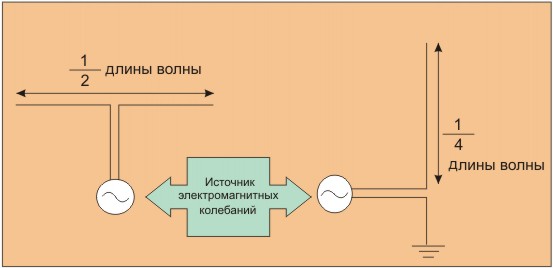
Their total length is half the wavelength, and the length of an individual segment is a quarter. If one end of the vibrator is directed vertically, the ground can be used instead of the second, or even the common conductor of the transmitter circuit.
For example, if the length of a vertical antenna is 1 meter, then for a radio wave 4 meters long (VHF band) it will present the greatest resistance. Accordingly, the efficiency of such an antenna will be maximum - precisely for radio waves of this length, both during reception and transmission.
To tell the truth, in the VHF range, the most reliable reception should be observed when the antenna is positioned horizontally. This is due to the fact that transmission in this range is, in fact, most often carried out using horizontally located half-wave vibrators. Therefore, a half-wave vibrator (and not a quarter-wave vibrator) will be a more efficient receiving antenna.
Use of any materials from this page is permitted provided there is a link to the site