Understanding the multivibrator
And there is no point in looking at me like that. This isn't the Japanese microprocessor thing you're thinking of. This is a completely harmless piece of hardware that can be used to make LEDs blink or beeps beep. Of course, its use is not limited to this. Especially when it comes to Japanese microprocessors... uh... sorry, I lost my train of thought.
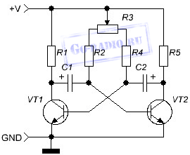
So, let's look at the diagram:
All the faces are familiar, aren't they? I think you've seen this diagram before... well, a lot of times, actually. However, now we will not only look at it, but also finally understand how it works and try to count some of its components.
So, we have a classic symmetrical multivibrator. He does what he generates square pulses, the parameters of which depend on resistors Rb1 And Rb2 and capacitors Cb1 And Cb2.
Strictly speaking, Rk1 And Rk2 also participate in this disgrace, however, their influence can be neutralized by the above-mentioned capacitors. Moreover, the denominations Rb and Rk are chosen in such a way that Rk
These same pulses can be removed from both the collector VT1 and VT2. Or you can do both at once, strictly speaking - no one interferes. Let's move on. We see the bridge. There is a crow on the bridge... but what is it today?!
Okay, let's look at the operation of the multivibrator before it starts again. In fact, a symmetrical multivibrator is a self-oscillator - that is, apart from turning on the power, nothing is required to start generation.
So let's say we turn on the power. Pulse generation begins.
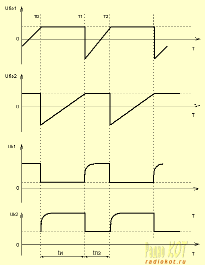
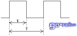
Now we will take a conditional debugger and stretch the generation time of one pulse enough to see with our own eyes what is happening there. Let us denote the moment in time at which we stopped the multivibrator to look through T0 (see the graph).
And at this very moment it turned out that transistor VT2 is closed, VT1 is open, capacitor Cb2 is discharged, and Cb1 is charged, but not completely, and the polarity of this charge is such that a negative voltage is applied to the base of VT2 (which is why it is closed).
What happens next is this: capacitor Cb1 continues to be charged from the power source through resistor Rb1 and transistor VT1, however, the voltage on it is not yet sufficient to open transistor VT2. And at the same time, capacitor Cb2 is charged through resistor Rk2 and the same open VT1. The capacitance of the capacitors is the same, however, since Rk
As Cb1 charges, the voltage at the base of VT2 increases. And at a certain moment, which we will designate T1, the voltage reaches a certain threshold and VT2 opens. Cb2 at this point is charged almost to the supply voltage.
Well, then complete chaos begins. As VT2 enters the active operating mode, its collector current increases and the collector-emitter voltage correspondingly decreases, which in turn causes the base current of VT1 to drop, and this leads to a decrease in the collector current of VT1, since the collector-emitter resistance increases. As a consequence, current begins to flow through Rk1 into the base of T2, which increases its base current.
In short, all together they kill the unfortunate VT1 and it closes. The whole process takes place almost instantly and like an avalanche, so that no one has time to understand anything. However, we have a picture that is already opposite to the initial moment - VT1 is closed, VT2 is open, Cb1 is almost discharged, and Cb2 is charged almost to the supply voltage.
Guess what happens next? Well, yes, exactly - Cb1 begins to charge through the circuit Rk1, VT2, and Cb2 maintains transistor VT1 in the closed state with a negative voltage. And when Cb1 is charged, everything will repeat exactly the opposite and this time VT2 will be closed. And so on until the power is turned off.
And now some formulas.
So, the pulse duration is approximately the following:
![]()
or ![]()
depending on which transistor the signal is taken from.
The frequency of the signal produced by the multivibrator can be estimated using the formula:
Where Rb And Cb- the value of base resistors and base capacitors in kilo-ohms and microfarads, respectively.
Or rather, one of the basic resistors and capacitors - there is no need to add their values.
And one more explanation on the schedule:
t and- pulse duration, which is determined by the charging time of capacitor C1,
tпз- pause duration determined by the charging time of C2.
This is if we connect the load to VT2. If to VT1, then exactly the opposite.
Well, to relieve your brain, here’s a simple flashing light circuit for two LEDs.
Capacitors, inductive elements. And from these bricks you can build anything you want. From a harmless children's toy that makes, for example, the sound of “meow”, to the guidance system of a ballistic missile with a multiple warhead for eight megaton charges.
One of the very well-known and often used circuits in electronics is a symmetrical multivibrator, which is an electronic device that produces (generates) oscillations in shape, approaching rectangular. The multivibrator is assembled on two transistors or logic circuits with additional elements. Essentially, this is a two-stage amplifier with a positive feedback circuit (POC). This means that the output of the second stage is connected through a capacitor to the input of the first stage. As a result, the amplifier turns into a generator due to positive feedback.
In order for the multivibrator to start generating pulses, it is enough to connect the supply voltage. Multivibrators can be symmetrical or asymmetrical.
The figure shows a circuit of a symmetrical multivibrator.
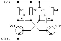
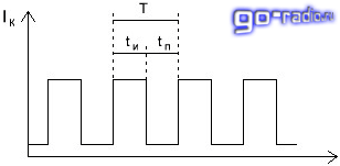
In a symmetrical multivibrator, the values of the elements of each of the two arms are absolutely the same: R1=R4, R2=R3, C1=C2. If you look at the oscillogram of the output signal of a symmetrical multivibrator, it is easy to notice that the rectangular pulses and pauses between them are the same in time. t pulse ( t and) = t pause ( t p). Resistors in the collector circuits of transistors do not affect the pulse parameters, and their value is selected depending on the type of transistor used.
The pulse repetition rate of such a multivibrator is easily calculated using a simple formula:
Where f is the frequency in hertz (Hz), C is the capacitance in microfarads (µF) and R is the resistance in kilo-ohms (kOhm). For example: C = 0.02 µF, R = 39 kOhm. We substitute it into the formula, perform the actions and get a frequency in the audio range approximately equal to 1000 Hz, or more precisely 897.4 Hz.
In itself, such a multivibrator is uninteresting, since it produces one unmodulated “squeak”, but if the elements select a frequency of 440 Hz, and this is the A note of the first octave, then we will get a miniature tuning fork, with which you can, for example, tune a guitar on a hike. The only thing you need to do is add a single transistor amplifier stage and a miniature speaker.
The following parameters are considered to be the main characteristics of a pulse signal:
Frequency. Unit of measurement (Hz) Hertz. 1 Hz – one oscillation per second. Frequencies perceived by the human ear are in the range of 20 Hz – 20 kHz.
Pulse duration. It is measured in fractions of a second: miles, micro, nano, pico and so on.
Amplitude. In the multivibrator under consideration, amplitude adjustment is not provided. Professional devices use both step and smooth amplitude adjustment.
Duty factor. The ratio of the period (T) to the pulse duration ( t). If the pulse length is 0.5 periods, then the duty cycle is two.
Based on the above formula, it is easy to calculate a multivibrator for almost any frequency with the exception of high and ultra-high frequencies. There are slightly different physical principles at work there.
In order for the multivibrator to produce several discrete frequencies, it is enough to install a two-section switch and five or six capacitors of different capacities, naturally identical in each arm, and use the switch to select the required frequency. Resistors R2, R3 also affect the frequency and duty cycle and can be made variable. Here is another multivibrator circuit with adjustable switching frequency.
Reducing the resistance of resistors R2 and R4 to less than a certain value, depending on the type of transistors used, can cause generation failure and the multivibrator will not work, therefore, in series with resistors R2 and R4, you can connect a variable resistor R3, which can be used to select the switching frequency of the multivibrator.
The practical applications of a symmetrical multivibrator are very extensive. Pulse computing technology, radio measuring equipment in the production of household appliances. A lot of unique medical equipment is built on circuits based on the same multivibrator.
Due to its exceptional simplicity and low cost, the multivibrator has found wide application in children's toys. Here is an example of a regular LED flasher.
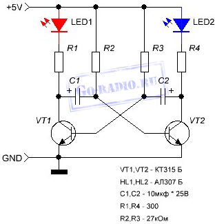
With the values of electrolytic capacitors C1, C2 and resistors R2, R3 indicated in the diagram, the pulse frequency will be 2.5 Hz, which means the LEDs will flash approximately twice per second. You can use the circuit proposed above and include a variable resistor together with resistors R2, R3. Thanks to this, it will be possible to see how the flash frequency of the LEDs will change when the resistance of the variable resistor changes. You can install capacitors of different ratings and observe the result.
The most commonly used is a symmetrical multivibrator, which is a device that generates rectangular oscillations. A transistor-based multivibrator has found its application in computer and household equipment, medical equipment and measuring equipment. Huge application in the production of children's toys.
Transistor multivibrator distinguished into:
- symmetrical;
- asymmetrical.
It consists of two transistors and additional elements that form a two-stage amplifier, the output of the stages is connected by a capacitor. Thanks to positive feedback, the amplifier is converted into an oscillator. When connected to power, the multivibrator generates pulses.
Symmetrical multivibrators have the same values of the elements of the two arms. Rectangular pulses and pauses are the same in time between them, based on the oscillogram. The transistor from the collector circuits of the resistor has no effect on the pulses. You can calculate the frequency of pulse movement using the formula: f = 700/(C1*R2), f – frequency in Hz, C – capacitance in µF, R – resistance in kOhm. It turns out to be approximately 1000 Hz. As a separate device, this multivibrator is not of particular interest, but by adding elements to it, you can create a musical tuning fork and tune a guitar. To do this, you need a speaker and an amplifier stage on a transistor.
It is believed that the following parameters are required to characterize a pulse signal: frequency, pulse duration, duty cycle and amplitude. If several discrete frequencies are needed, you need to install a two-section switch and several capacitors, identical in each arm and different in capacitance. Select the desired frequency using the switch.
Circuit of a symmetrical multivibrator using transistors
Single-ended multivibratorson transistors of different conductivity is endowed with many interesting properties. During operation, the current consumed by the locked transistors is small, and during operation, two transistors are either open or locked at the same time. This results in the creation of cost-effective moisture indicators used in the care of infants. Using a multivibrator, you can make a simple generator for testing receivers.
Radio circuits for beginner radio amateurs
In this article we present several devices based on one circuit - an asymmetrical multivibrator using transistors of different conductivities.
flasher
Using this circuit, you can assemble a device with a blinking light bulb (see Fig. 1) and use it for various purposes. For example, install it on a bicycle to power turn lights, or in a lighthouse model, a signal light, or on a car or ship model as a flashing light.
The load of an asymmetrical multivibrator assembled on transistors T1, T2 is light bulb L1. The pulse repetition rate is determined by the capacitance value of capacitor C1 and resistors R1, R2. Resistor R1 limits the maximum flash frequency, and resistor R2 can be used to smoothly change their frequency. You need to start working from the maximum frequency, which corresponds to the top position of the resistor R2 slider in the diagram.
Please note that the device is powered by a 3336L battery, which produces 3.5 V under load, and the L1 light bulb is used at a voltage of only 2.5 V. Will it burn out? No! The duration of its glow is very short, and the thread does not have time to overheat. If the transistors have a high gain, then instead of a 2.5 V x 0.068 A light bulb, you can use a 3.5 V x 0.16 A light bulb. Transistors like MP35-MP38 are suitable for transistor T1, and transistors like MP39-MP42 are suitable for T2.
Metronome
If you install a loudspeaker in the same circuit instead of a light bulb, you will get another device - an electronic metronome. It is used in teaching music, for keeping time during physical experiments, and in photographic printing.
If you slightly change the circuit - reduce the capacitance of capacitor C1 and introduce resistor R3, then the pulse duration of the generator will increase. The sound will increase (Fig. 2). This device can serve as a house bell, a model horn, or a children's pedal car. (In the latter case, the voltage must be increased to 9 V.) And it can also be used for teaching Morse code. Only then, instead of the Kn1 button, you need to install a telegraph key. The sound tone is selected by capacitor C1 and resistor R2. The larger R3, the louder the sound of the generator. However, if its value is more than one kilo-ohm, then oscillations in the generator may not occur.
The generator uses the same transistors as in the previous circuit, and headphones or a head with a coil resistance of 5 to 65 Ohms are used as a loudspeaker.
Humidity indicator
An asymmetrical multivibrator using transistors of different conductivities has an interesting property: during operation, both transistors are either open or locked at the same time. The current consumed by the switched-off transistors is very small. This makes it possible to create cost-effective indicators of changes in non-electrical quantities, such as humidity indicators. The schematic diagram of such an indicator is shown in Figure 3. As can be seen from the diagram, the generator is constantly connected to the power source, but does not work, since both transistors are locked. Reduces current consumption and resistor R4. A humidity sensor is connected to sockets G1, G2 - two thin tinned wires 1.5 cm long. They are sewn to the fabric at a distance of 3-5 mm from each other. The resistance of the dry sensor is high. When wet it falls. The transistors open, the generator starts working. To reduce the volume, you need to reduce the supply voltage or the value of resistor R3. This humidity indicator can be used when caring for newborn babies.
Humidity indicator with sound and light signal
If you expand the circuit a little, the humidity indicator will emit light simultaneously with the sound signal - light bulb L1 will start to light up. In this case, as can be seen from the diagram (Fig. 4), two asymmetrical multivibrators on transistors of different conductivities are installed in the generator. One is assembled on transistors T1, T2 and is controlled by a humidity sensor connected to sockets G1, G2. The load of this multivibrator is lamp L1. The voltage from the collector T2 controls the operation of the second multivibrator, assembled on transistors T3, T4. It works as an audio frequency generator, and loudspeaker Gr1 is turned on at its output. If there is no need to give a sound signal, then the second multivibrator can be turned off.
The transistors, lamp and loudspeaker used in this humidity indicator are the same as in previous devices.
Siren simulator
Interesting devices can be built using the dependence of the frequency of an asymmetrical multivibrator on transistors of different conductivity on the base current of transistor T1. For example, a generator that simulates the sound of a siren. Such a device can be installed on a model of an ambulance, fire truck, or rescue boat.
The schematic diagram of the device is shown in Figure 5. In the initial position, the Kn1 button is open. Transistors are locked. The generator is not working. When the button is closed, capacitor C2 is charged through resistor R4. The transistors open and the multivibrator starts working. As capacitor C2 charges, the base current of transistor T1 increases and the frequency of the multivibrator increases. When the button is opened, everything repeats in the reverse order. The siren sound is simulated by periodically closing and opening the button. The rate of rise and fall of sound is selected by resistor R4 and capacitor C2. The siren tone is set by resistor R3, and the sound volume by selecting resistor R5. The transistors and loudspeaker are selected the same as in previous devices.
Transistor tester
Considering that this multivibrator uses transistors of different conductivities, you can use it as a device for testing transistors by replacement. The schematic diagram of such a device is shown in Figure 6. The circuit of a sound generator is taken as a basis, but a light pulse generator can be used with equal success.
Initially, by closing the Kn1 button, check the operation of the device. Depending on the type of conductivity, connect the transistor under test to sockets G1 - G3 or G4-G6. In this case, use switch P1 or P2. If there is sound in the loudspeaker when you press the button, then the transistor is working.
As switches P1 and P2, you can take toggle switches with two switching contacts. The figure shows the switches in the "Control" position. The device is powered by a 3336L battery.
Sound generator for testing amplifiers
Based on the same multivibrator, you can build a fairly simple generator for testing receivers and amplifiers. Its circuit diagram is shown in Figure 7. Its difference from a sound generator is that instead of a loudspeaker, a 7-step voltage level regulator is switched on at the output of the multivibrator.
E. TARASOV
Rice Y. CHESNOKOBA
YUT For skillful hands 1979 No. 8