Multivibrator.
The first circuit is the simplest multivibrator. Despite its simplicity, its scope is very wide. None electronic device can't do without it.
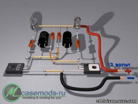
The first figure shows its circuit diagram.
LEDs are used as a load. When the multivibrator is working, the LEDs switch.
For assembly you will need a minimum of parts:
1. Resistors 500 Ohm - 2 pieces
2. Resistors 10 kOhm - 2 pieces
3. Electrolytic capacitor 47 uF for 16 volts - 2 pieces
4. Transistor KT972A - 2 pieces
5. LED - 2 pieces
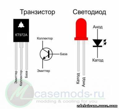
KT972A transistors are composite transistors, that is, their housing contains two transistors, and it is highly sensitive and can withstand significant current without heat sink.
Once you have purchased all the parts, arm yourself with a soldering iron and start assembling. To conduct experiments, you don’t need to make a printed circuit board; you can assemble everything wall-mounted. Solder as shown in the pictures.
Let your imagination tell you how to use the assembled device! For example, instead of LEDs you can install a relay, and with this relay you can switch more powerful load. If you change the values of resistors or capacitors, the switching frequency will change. By changing the frequency you can achieve very interesting effects, from a squeak in the dynamics to a pause for many seconds..
Photo relay.
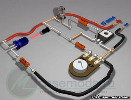
And this is a diagram of a simple photo relay. This device can be successfully used wherever you want, to automatically illuminate the DVD tray, to turn on the light, or to alarm against intrusion into a dark closet. Two schematic options are provided. In one embodiment, the circuit is activated by light, and in the other by its absence.
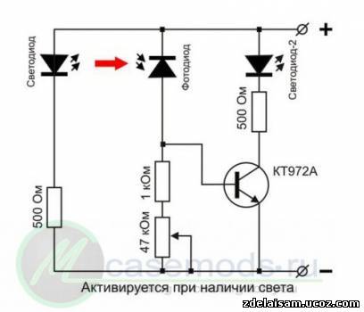
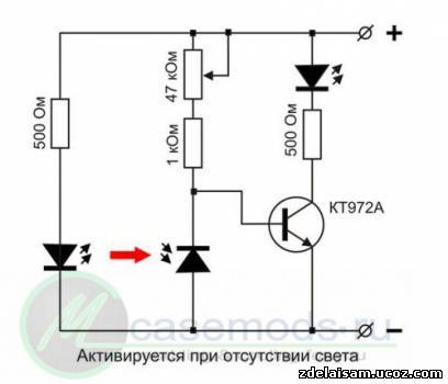
It works like this: when light from the LED hits the photodiode, the transistor will open and LED-2 will start to glow. The sensitivity of the device is adjusted using a trimming resistor. As a photodiode, you can use a photodiode from an old ball mouse. LED - any infrared LED. The use of infrared photodiode and LED will avoid interference from visible light. Any LED or a chain of several LEDs is suitable as LED-2. An incandescent lamp can also be used. And if instead of an LED you put an electromagnetic relay, then you can control powerful lamps incandescent, or some other mechanisms.
The figures show both circuits, the pinout (location of the legs) of the transistor and LED, as well as the wiring diagram.
If there is no photodiode, you can take an old MP39 or MP42 transistor and cut off its housing opposite the collector, like this:
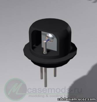
Instead of a photodiode, you will need to include in the circuit p-n junction transistor. You will have to determine experimentally which one will work better.
Power amplifier based on TDA1558Q chip.
This amplifier has an output power of 2 X 22 watts and is simple enough for beginner hams to replicate. This circuit will be useful for you for homemade speakers, or for a homemade music center, which can be made from an old MP3 player.
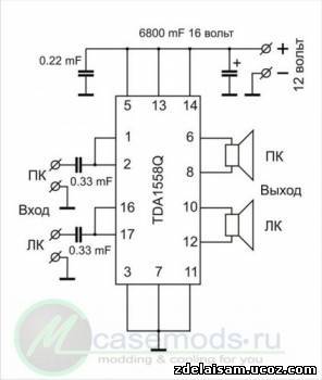
To assemble it you will need only five parts:
1. Microcircuit - TDA1558Q
2. Capacitor 0.22 uF
3. Capacitor 0.33 uF – 2 pieces
4. Electrolytic capacitor 6800 uF at 16 volts
The microcircuit has a fairly high output power and will need a radiator to cool it. You can use a heatsink from the processor.
The entire assembly can be carried out by surface mounting without the use of printed circuit board. First, you need to remove pins 4, 9 and 15 from the microcircuit. They are not used. The pins are counted from left to right if you hold it with the pins facing you and the markings facing up. Then carefully straighten the leads. Next, bend pins 5, 13 and 14 up, all these pins are connected to the power positive. The next step is to bend pins 3, 7 and 11 down - this is the power supply minus, or “ground”. After these manipulations, screw the chip to the heat sink using thermal conductive paste. The pictures show the installation from different angles, but I will still explain. Pins 1 and 2 are soldered together - this is the input of the right channel, a 0.33 µF capacitor must be soldered to them. The same must be done with pins 16 and 17. The common wire for the input is the minus power supply or ground.
Varieties of one circuit (asymmetrical multivibrator)
In this article we present several devices based on one circuit - single-ended multivibrator on transistors of different conductivities.
Using this circuit as a contactless device, you can assemble a device with a flashing light from an electric light bulb (see Fig. 1) and use it for various purposes. For example, install it on a bicycle to power turn lights, or in a model of a lighthouse, a signal light, or on a car. or ship models as a flashing light.
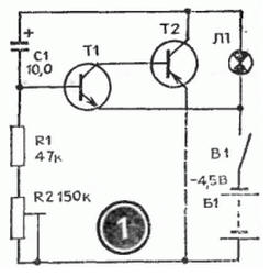
The load of an asymmetrical multivibrator assembled on transistors T1, T2 is light bulb L1. The pulse repetition rate is determined by the capacitance value of capacitor C1 and resistors R1, R2. Resistor R1 limits the maximum flash frequency, and resistor R2 can be used to smoothly change their frequency. You need to start working from the maximum frequency, which corresponds to the top position of the resistor R2 slider in the diagram.
Please note that the device is powered by a 3336L battery, which produces 3.5 V under load, and the L1 light bulb is used at a voltage of only 2.5 V. Will it burn out? No! The duration of its glow is very short, and the thread does not have time to overheat. If the transistors have a high gain, then instead of a 2.5 V x 0.068 A light bulb, you can use a 3.5 V x 0.16 A light bulb. Transistors like MP35-MP38 are suitable for transistor T1, and transistors like MP39-MP42 are suitable for T2.
If you install a loudspeaker in the same circuit instead of a light bulb, you will get another device - an electronic metronome. It is used in teaching music, for keeping time during physical experiments, and in photographic printing.
If you slightly change the circuit - reduce the capacitance of capacitor C1 and introduce resistor R3, then the pulse duration of the generator will increase. The sound will increase (Fig. 2).
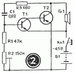
This device can serve as a house bell, a model horn, or a children's pedal car. (In the latter case, the voltage must be increased to 9 V.) And it can also be used for teaching Morse code. Only then, instead of the Kn1 button, you need to install a telegraph key. The sound tone is selected by capacitor C1 and resistor R2. The larger R3, the louder sound generator However, if its value is more than one kilo-ohm, then oscillations in the generator may not occur.
The generator uses the same transistors as in the previous circuit, and headphones or a head with a coil resistance of 5 to 65 Ohms are used as a loudspeaker.
An asymmetrical multivibrator using transistors of different conductivities has an interesting property: during operation, both transistors are either open or locked at the same time. The current consumed by the switched-off transistors is very small. This makes it possible to create cost-effective indicators of changes in non-electrical quantities, such as humidity indicators. Schematic diagram such an indicator is shown in Figure 3.
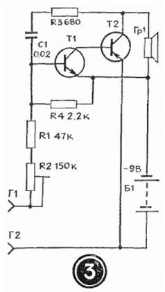
As can be seen from the diagram, the generator is constantly connected to the power source, but does not work because both transistors are locked. Reduces current consumption and resistor R4. A humidity sensor is connected to sockets G1, G2 - two thin tinned wires 1.5 cm long. They are sewn to the fabric at a distance of 3-5 mm from each other. The resistance of the dry sensor is high. When wet it falls. The transistors open, the generator starts working. To reduce the volume, you need to reduce the supply voltage or the value of resistor R3. This humidity indicator can be used when caring for newborn babies.
If you expand the circuit a little, the humidity indicator will emit light simultaneously with the sound signal - light bulb L1 will start to light up. In this case, as can be seen from the diagram (Fig. 4), two asymmetrical multivibrators on transistors of different conductivities are installed in the generator. One is assembled on transistors T1, T2 and is controlled by a humidity sensor connected to sockets G1, G2. The load of this multivibrator is lamp L1. The voltage from the collector T2 controls the operation of the second multivibrator, assembled on transistors T3, T4. It works as an audio frequency generator, and loudspeaker Gr1 is turned on at its output. If there is no need to give a sound signal, then the second multivibrator can be turned off.
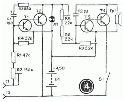
The transistors, lamp and loudspeaker used in this humidity indicator are the same as in previous devices.
Interesting devices can be built using the dependence of the frequency of an asymmetrical multivibrator on transistors of different conductivity on the base current of transistor T1. For example, a generator that simulates the sound of a siren. Such a device can be installed on a model of an ambulance, fire truck, or rescue boat.
The schematic diagram of the device is shown in Figure 5.
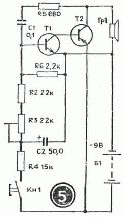
In the initial position, the Kn1 button is open. Transistors are locked. The generator is not working. When the button is closed, capacitor C2 is charged through resistor R4. The transistors open and the multivibrator starts working. As capacitor C2 charges, the base current of transistor T1 increases and the frequency of the multivibrator increases. When the button is opened, everything repeats in the reverse order. The siren sound is simulated by periodically closing and opening the button. The rate of rise and fall of sound is selected by resistor R4 and capacitor C2. The siren tone is set by resistor R3, and the sound volume by selecting resistor R5. The transistors and loudspeaker are selected the same as in previous devices.
Considering that this multivibrator uses transistors of different conductivities, you can use it as a device for testing transistors by replacement. The schematic diagram of such a device is shown in Figure 6. The circuit of a sound generator is taken as a basis, but a light pulse generator can be used with equal success.
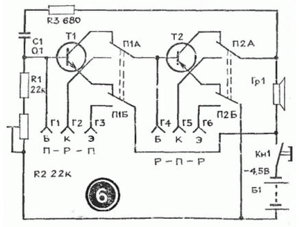
Initially, by closing the Kn1 button, check the operation of the device. Depending on the type of conductivity, connect the transistor under test to sockets G1 - G3 or G4-G6. In this case, use switch P1 or P2. If there is sound in the loudspeaker when you press the button, then the transistor is working.
As switches P1 and P2, you can take toggle switches with two switching contacts. The figure shows the switches in the "Control" position. The device is powered by a 3336L battery.
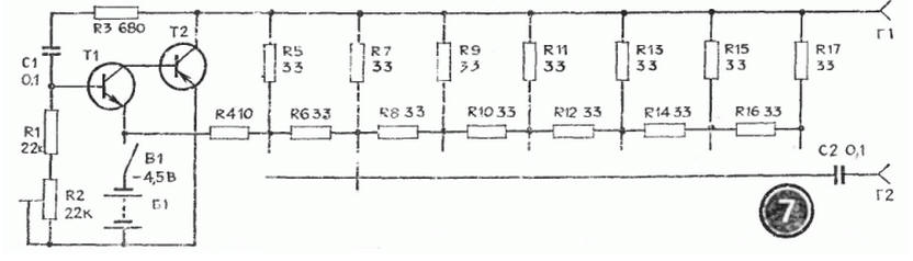
Based on the same multivibrator, you can build a fairly simple generator for testing receivers and amplifiers. Its circuit diagram is shown in Figure 7. Its difference from a sound generator is that instead of a loudspeaker, a 7-step voltage level regulator is switched on at the output of the multivibrator.
The multivibrator circuit shown in Figure 1 is a cascade connection of transistor amplifiers where the output of the first stage is connected to the input of the second through a circuit containing a capacitor and the output of the second stage is connected to the input of the first through a circuit containing a capacitor. Multivibrator amplifiers are transistor switches that can be in two states. The multivibrator circuit in Figure 1 differs from the trigger circuit discussed in the article “trigger on electronic transistor switches”. With what he has in chains feedback reactive elements so the circuit can generate non-sinusoidal oscillations. You can find the resistance of resistors R1 and R4 from relations 1 and 2:
Where I KBO = 0.5 µA - maximum reverse current collector of transistor KT315A,
Ikmax=0.1A is the maximum collector current of the KT315a transistor, Up=3V is the supply voltage. Let's choose R1=R4=100Ohm. Capacitors C1 and C2 are selected depending on the required oscillation frequency of the multivibrator.
Figure 1 - Multivibrator based on KT315A transistors
You can relieve the voltage between points 2 and 3 or between points 2 and 1. The graphs below show how approximately the voltage will change between points 2 and 3 and between points 2 and 1.
T - oscillation period, t1 - time constant of the left arm of the multivibrator, t2 - time constant of the right arm of the multivibrator can be calculated using the formulas:
You can set the frequency and duty cycle of the pulses generated by the multivibrator by changing the resistance of trimming resistors R2 and R3. You can also replace capacitors C1 and C2 with variable (or trimmer) capacitors and, by changing their capacitance, set the frequency and duty cycle of the pulses generated by the multivibrator, this method is even more preferable, so if there are trimmer (or better variable) capacitors, then it is better to use them, and in place variable resistors Set R2 and R3 constant. The photo below shows the assembled multivibrator:
In order to make sure that the assembled multivibrator works, a piezodynamic speaker was connected to it (between points 2 and 3). After applying power to the circuit, the piezo speaker began to crackle. Changes in the resistance of the tuning resistors led either to an increase in the frequency of the sound emitted by the piezodynamics, or to its decrease, or to the fact that the multivibrator stopped generating.
A program for calculating the frequency, period and time constants, duty cycle of pulses taken from a multivibrator:
If used Internet browser Explorer and it blocks the program, you need to allow the blocked content.
js disabled
Other multivibrators:


