Instructions for repairing faults in the lighting system of the Lada 2110, the procedure for assembling and disassembling headlights and replacing lamps of the Lada 2111, adjusting the headlights of the VAZ 2111, VAZ 2112, VAZ 2110. External and internal lighting Parts of the car lighting system VAZ 2110, VAZ 2111, VAZ 2112 electrical equipment repair lighting, troubleshooting
Brake and reverse lamps, interior and trunk lighting of VAZ 2110, VAZ 2111, VAZ 2112, Lada Ten
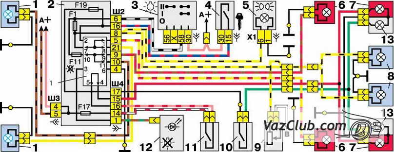
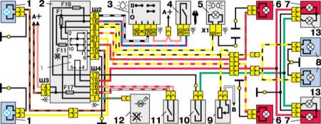
External lighting switching diagram
1 - side light lamps in headlights
2 - mounting block
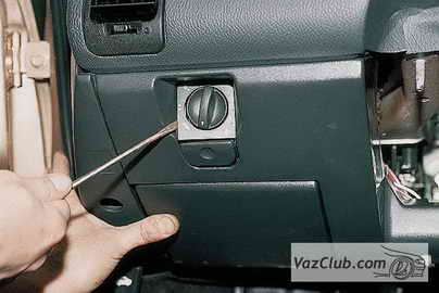
3 - outdoor lighting switch
4 - ignition switch
5 -- indicator lamp for external lighting in the instrument cluster
6 - side light lamps in the external rear lights
7 -- brake light lamps in the inner rear lights
8 -- license plate lights
9 -- instrument lighting switch
10 -- reverse light switch
11 - brake light switch
12 -- on-board control system unit
13 -- reverse lamps in the inner rear lights
K1 - lamp health monitoring relay (contact jumpers are shown inside the relay, which must be installed in the absence of a relay)
A - to power supplies
B -- to instrument lighting lamps
The front side light lamps are located in the headlights, the rear lamps are located in the external rear lights (on the wings of the VAZ 2111). Brake and reverse lamps are located in the inner rear lights on the trunk lid. (To remove the brake light switch, see Removing the Vacuum Booster and Brake Pedal Assembly). The license plate lights are located on the bumper.
The parking light is on when the exterior light switch is pressed. The side light lamps of the VAZ 2112 and the brake light are powered through relay K1 for monitoring the health of the lamps in mounting block. If any of the lamps burns out or the contact in the socket or supply circuit is broken, the corresponding indicator lights up in the control unit. If there is no lamp control relay, there must be jumpers instead, otherwise the lamps will not light.
The license plate lamps turn on simultaneously with the exterior lighting, but are connected bypassing the control relay, so their serviceability is not diagnosed.
The backlight lamp for the VAZ 2110 glove box is turned on when the ignition is turned on by a switch under the box lid.
Voltage is also supplied to the switches of the interior lamp and the driver's individual lamp when the ignition of the VAZ 2110 is turned on. In addition, the interior lamp lights up if one of the doors is open and the lamp switch is in the appropriate position. A few seconds after closing the door, the brightness of the lamp decreases and it goes out. This is controlled by the display unit of the on-board control system.
The instrument lighting turns on simultaneously with the exterior lighting. The brightness of the backlight lamps is controlled by a rheostat on the instrument panel of the VAZ 2111.
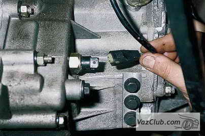
The reversing lamps light up if the ignition of the VAZ 2112 is turned on and the reverse switch located on the gearbox is closed.
The trunk lighting turns on simultaneously with the side light lamps.
Car lighting VAZ 2110, VAZ 2111, VAZ 2112
 Lighting schemeHeadlights and lighting VAZ 2110, VAZ 2111, VAZ 2112 |
 Removing and installing headlightsDismantling and assembling headlight unit, replacing lamps VAZ 2110, VAZ 2111, VAZ 2112 |
Headlight hydraulic correctorHydrocorrector of headlights VAZ 2110, VAZ 2111, VAZ 2112 |
 Replacing the hydraulic corrector master cylinderRemoving and installing the main cylinder of the headlight hydraulic corrector VAZ 2110, VAZ 2111, VAZ 2112 |
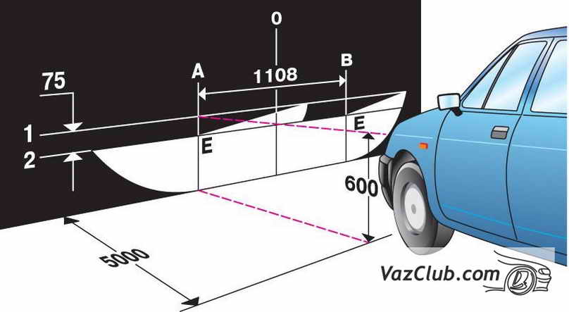 Adjusting the headlightsAdjusting the headlights of VAZ 2110, VAZ 2111, VAZ 2112 cars |
External and internal lightingBrake and reverse lamps, interior and trunk lighting of VAZ 2110, VAZ 2111, VAZ 2112 |
Direction indicatorsDirection indicators VAZ 2110, VAZ 2111, VAZ 2112 |
 Fog lightsReplacing the side light and fog light VAZ 2110, VAZ 2111, VAZ 2112 |
 Replacing the side turn signalRemoving and installing the side direction indicator VAZ 2110, VAZ 2111, VAZ 2112 |
 Replacing the reverse light switchRemoving and installing the reverse light switch VAZ 2110, VAZ 2111, VAZ 2112 |
 Replacing reverse and brake lightsRemoving and installing a brake light and reverse light for VAZ 2110, VAZ 2111, VAZ 2112 |
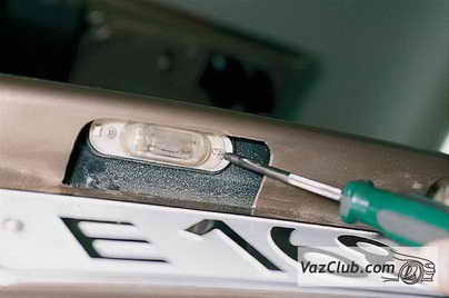 Rear license plate light replacementRemoving and installing the rear license plate lamp for VAZ 2110, VAZ 2111, VAZ 2112 |
Instructions for repairing faults in the lighting system of the Lada 2110, the procedure for assembling and disassembling the headlights and replacing the lamps of the Lada 2111, adjusting the headlights of the VAZ 2111, VAZ 2112, VAZ 2110. Lighting diagram Details of the vehicle lighting system VAZ 2110, VAZ 2111, VAZ 2112 repair of electrical equipment lighting, troubleshooting
Headlights and lighting for cars VAZ 2110, VAZ 2111, VAZ 2112, Lada Ten
The VAZ 2110 is equipped with two block headlights manufactured by Bosch or JSC Avtosvet, which combine low and high beam headlights, side (parking) light lamps and direction indicators. Headlight units vary in design. Low beam headlight "Avtosvet" - with a flat screen and a lens between the lamp and the lens, the lens of the headlight unit is glued to the body, the side light lamp is located in the main beam headlight. Low beam headlight VAZ 2111 Bosch - without a lens, with a screen-cap on the lamp, side light lamp - in the low beam headlight. The turn indicators for both headlight units are the same, the mounting points are the same: at the top - with bolts to the upper cross member of the radiator frame of the VAZ 2112, at the bottom - with a nut to the stud on the mudguard bracket and a bolt - to the radiator frame strut.
The headlights are equipped with single-filament low and high beam lamps. When you turn on the low beam of the headlights, the low beam lamps of the VAZ 2112 light up, and when you turn on the high beam, all the lamps (both low and high beam) light up.
The voltage for the low and high beam lamps is supplied respectively through relays K4 and K5 of type 904.3747-10, located in the mounting block. The relay switching voltage at a temperature of 20±5°C is no more than 8 V, the winding resistance is 85±8.5 Ohms. Voltage is supplied to the relay windings if the VAZ 2110 external lighting switch key is fully pressed (then the choice is between low and high beam– depending on the position of the steering column switch for headlights) or – regardless of the position of the switch – if the driver pulls the steering column switch towards himself (then the high beam headlights).
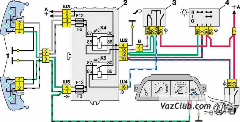
Connection diagrams for headlights with single-filament low beam lamps
1 - block headlights
2 - mounting block
3 - headlight switch VAZ 2111
4 - external lighting switch
5 - ignition switch
6 - instrument cluster with high beam headlight warning lamp
A - to power supplies
K4 - relay for low beam headlights
K5 - headlight high beam relay
Car lighting VAZ 2110, VAZ 2111, VAZ 2112
Lighting schemeHeadlights and lighting VAZ 2110, VAZ 2111, VAZ 2112 |
Removing and installing headlightsDismantling and assembling headlight unit, replacing lamps VAZ 2110, VAZ 2111, VAZ 2112 |
Headlight hydraulic correctorHydrocorrector of headlights VAZ 2110, VAZ 2111, VAZ 2112 |
Replacing the hydraulic corrector master cylinderRemoving and installing the main cylinder of the headlight hydraulic corrector VAZ 2110, VAZ 2111, VAZ 2112 |
Adjusting the headlightsAdjusting the headlights of VAZ 2110, VAZ 2111, VAZ 2112 cars |
 External and internal lightingBrake and reverse lamps, interior and trunk lighting of VAZ 2110, VAZ 2111, VAZ 2112 |
Direction indicatorsDirection indicators VAZ 2110, VAZ 2111, VAZ 2112 |
Fog lightsReplacement of side and fog light of VAZ 2110, VAZ 2111, VAZ 2112 |
Replacing the side turn signalRemoving and installing the side direction indicator VAZ 2110, VAZ 2111, VAZ 2112 |
Replacing the reverse light switchRemoving and installing the reverse light switch VAZ 2110, VAZ 2111, VAZ 2112 |
Replacing reverse and brake lightsRemoving and installing a brake light and reverse light for VAZ 2110, VAZ 2111, VAZ 2112 |
Rear license plate light replacementRemoving and installing the rear license plate lamp for VAZ 2110, VAZ 2111, VAZ 2112 |
 Luggage compartment lightRemoving and installing the luggage compartment lamp of VAZ 2110, VAZ 2111, VAZ 2112 |
Lighting and light signaling
The car is equipped with two block headlights manufactured by Bosch or JSC Avtosvet, which combine low and high beam headlights, side (parking) light lamps and direction indicators. Headlight units vary in design. Low beam headlight "Avtosvet" - with a flat screen and a lens between the lamp and the lens, the lens of the headlight unit is glued to the body, the side light lamp is located in the main beam headlight. Bosch low beam headlight - without lens, with a screen cap on the lamp, side light lamp - in the low beam headlight. The turn indicators for both headlight units are the same, the mounting points are the same: at the top - with bolts to the upper cross member of the radiator frame, at the bottom - with a nut to the stud on the mudguard bracket and a bolt - to the radiator frame strut.
The headlights are equipped with single-filament low and high beam lamps. When you turn on the low beam of the headlights, the low beam lamps light up, and when you turn on the high beam, all the lamps (both low and high beam) light up.
The voltage for the low and high beam lamps is supplied respectively through relays K4 and K5 of type 904.3747-10, located in the mounting block. The relay switching voltage at a temperature of 20±5°C is no more than 8 V, the winding resistance is 85±8.5 Ohms. Voltage is supplied to the relay windings if the exterior lighting switch key is fully pressed (then the choice between low and high beams depends on the position of the steering column headlight switch) or, regardless of the position of the switch, if the driver pulls the steering column switch towards himself (then the high beam turns on headlights).
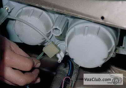
Removing and disassembling the headlamp, replacing lamps
Connection diagrams for headlights with single-filament low beam lamps
- Remove the radiator grille.
- We glue the new glass using a special sealant.
- To remove the high beam and side beam lamps, remove the second headlight cover.
We assemble and install the headlamp in the reverse order.
The directions of the light beams of the headlights are adjusted by rotating screws that rotate the optical element in the vertical and horizontal planes.
Headlight hydrocorrector
The headlight hydraulic corrector is used to change the angle of the headlights depending on the vehicle load. It consists of a master cylinder mounted on the instrument panel, slave cylinders mounted on the headlights, and connecting pipes. The cylinders and tubes are filled with a special liquid with a low freezing point and do not communicate with the atmosphere.
The hydraulic corrector is non-separable and cannot be repaired. If the pistons in the cylinders become sour, there are leaks from the cylinders or tubes, and also if the stroke of the actuator rods (in headlights) differs from the value of 7±0.5 mm, replace the hydraulic corrector assembly.
Removing the headlight hydraulic corrector master cylinder
|
EXECUTION ORDER |
|
|
Exterior lighting, brake and reverse lights, interior and trunk lighting
External lighting switching diagram
 |
|
|
1 - side light lamps in headlights |
9 -- instrument lighting switch |
The front side light lamps are located in the headlights, the rear lamps are located in the external rear lights (on the fenders of the car). Brake and reverse lamps are located in the inner rear lights on the trunk lid. (To remove the brake light switch, see Removing the Vacuum Booster and Brake Pedal Assembly). The license plate lights are located on the bumper.
The parking light is on when the exterior light switch is pressed. The side light and brake light lamps are powered through relay K1 for monitoring the health of the lamps in the mounting block. If any of the lamps burns out or the contact in the socket or supply circuit is broken, the corresponding indicator lights up in the control unit. If there is no lamp control relay, there must be jumpers instead, otherwise the lamps will not light.
The license plate lamps turn on simultaneously with the exterior lighting, but are connected bypassing the control relay, so their serviceability is not diagnosed.
The glove box illumination lamp is turned on when the ignition is turned on by a switch under the box lid.
Voltage is also supplied to the switches of the interior courtesy lamp lamps and the driver's individual courtesy lamp when the ignition is turned on. In addition, the interior lamp lights up if one of the doors is open and the courtesy light switch is in the appropriate position. A few seconds after closing the door, the brightness of the lamp decreases and it goes out. This is controlled by the display unit of the on-board control system.
The instrument lighting turns on simultaneously with the exterior lighting. The brightness of the backlights is controlled by a rheostat on the instrument panel.
The reverse lamps come on when the ignition is turned on and the reverse switch located on the transmission is closed.
The trunk lighting turns on simultaneously with the side light lamps.
Direction indicators
The direction indicators (left or right) are activated by the steering column switch.
The hazard warning mode (all direction indicators flash) is activated by pressing the corresponding button. The blinking of lamps in this mode is ensured by a relay-breaker K3 type 493.3747 in the mounting block.
If one of the turn signal lamps burns out, the blinking frequency of the remaining lamps and the warning lamp doubles. In normal mode, the blinking frequency should be 90±30 cycles per minute at an ambient temperature of –40 to +65°C and a voltage of 10.8 to 15 V.
Diagram for switching on direction indicators and hazard warning lights
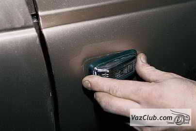
Removing the parking light, fog light and turn signal
 |
|
Removing the side turn signal and replacing the lamp
 |
|
Removing the reverse light switch
|
EXECUTION ORDER |
||
|
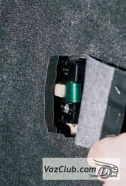
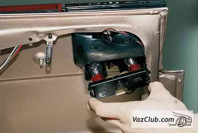
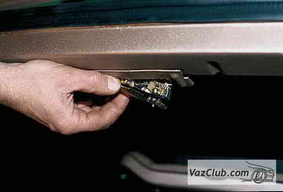
Removing the brake light and reverse light
|
On the VAZ 2110, as on other car models, the brake lights play important function to warn other participants traffic about braking or reducing speed. If the brake lights on a VAZ 2110 are not lit, this reduces the safety of using the car and can lead to emergency situation. In this case, you should not immediately take the car to a workshop, because most often you can find the cause of such a breakdown and fix it yourself. To cope with such a problem on your own, it is important to understand how the brake lights on the VAZ 2110 work.
Scheme of operation of stop lights
The stops on VAZ cars work according to the same, fairly simple scheme. The main element of this unit is the sensor responsible for turning on the brake light. When the sensor is triggered, the brake lights in the rear of the car light up. When braking stops, the lamp stops lighting. If the brake lights on a VAZ 2110 do not light up, the first thing you need to do is make sure that the lamps have not burned out. The brake light circuit works as follows: voltage from battery is directed to the stop switch, the closure of which allows current to pass through the filament of lamps connected to each other. Voltage is then sent to the negative of the battery, allowing the lights to light up.
On most older VAZ cars, the brake light sensor is located in the area of the brake system line. In this case, the process of closing the contacts was carried out by increasing the air or liquid pressure in the system. The main disadvantage of this connection was that the brake lights came on along with the brake pads when the car began to slow down. On modern models, such as the VAZ 2110, the stop sensor is connected to the brake pedal. This made it possible to turn on the lamp exactly at the moment the driver presses the brake. This design connects the brake lights at the moment the brake pedal free travel is selected, before deceleration begins.
Reasons for a non-working brake light
If the brake light on a VAZ 2110 does not light up, the first thing you need to do is check whether the fuse responsible for protecting the signal lamp circuit has blown. Then we take a test lamp and check whether there is power to the stop sensor. If during such a test the indicator lamp does not light up, it means that the fuse has failed or the wire leading to the brake light switch from the fuse has broken. When performing this test, it is important to ensure that power is being supplied to and routed from the fuse. If necessary, we replace broken or burnt wires and eliminate broken contacts in the connecting circuit leading to the sensor or fuse. If power is present at one of the terminals, you can remove both wires and connect them copper wire. In this case, the warning lights will light up.
If the lamps light up during the test, then we can talk about a sensor malfunction. This spare part cannot be repaired, so it must be replaced. If it turns out that the sensor is working, then you need to look for a break in the wiring or a malfunction of the lamps. In this case, we take a test lamp and check whether there is power at the plug responsible for operation rear lights. If power is supplied, it is most likely that the brake lights on the VAZ 2110 do not work due to faulty lamps. If there is no power, you need to find an open circuit or poor contact in the system between the stop switch and the warning light. It happens that a new fuse is installed, but it immediately blows. In this case we can talk about the presence short circuit that needs to be found and eliminated.