The heating system requires periodic adjustment. The coolant must be evenly distributed over it, which means that special equipment is required that will help make adjustments correctly. This device is often a balancing valve.
By hydraulic balancing, the coolant is distributed throughout all areas of the heating circuit without exception.
Simple system options involve adjusting the coolant flow by selecting the optimal pipe diameter around the perimeter.
Special washers are also used, the passage in which is designed for uninterrupted flow of water and uniform heating of the elements.
Each of these options was used in old-style heating circuits. New method– installation of a balancing valve, which is a regular valve that regulates the amount of coolant supplied.
Design Feature
A high-quality part includes reliable components:
- Robust brass body with threaded fittings for connecting pipes. Inside the product there is a saddle in the form of a special vertical channel.
- Adjustment spindle. The working part is represented by a cone, which is screwed into the saddle. As a result of spindle activation, the coolant flow is blocked.
- Rubber O-rings.
- The cap is usually made of plastic. There are also metal options.
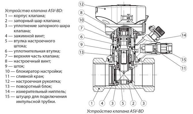
A distinctive feature of the device is the presence of two special fittings.
They are responsible for the following functions:
- Determine the pressure inside the system both before and after the valve.
- Connect a capillary type tube.
Each of the fittings measures the pressure, and if a difference in values is detected on the control mechanism, the water flow is calculated.
Operating principle
Balancing valves are designed to help achieve maximum performance from all heating elements system, and also adjust it at any time.
The problem of uneven distribution of heating in multi-circuit heating systems occurs quite often. The coolant flow is similar to electric current, so it flows along the path of minimum resistance. It turns out that the farther you are from the boiler, the less heat consumption is compared to the distance from it. To equalize this indicator, craftsmen use a balancing valve.
Sometimes, in order to save money, an ordinary tap is installed to adjust the level of cross-country ability, but this setting is more rough and inaccurate, while the balancing valve copes with its task perfectly. The choice is influenced by the result that residents strive to obtain. Often, craftsmen install a ball valve with a long switch and turn the lever in different directions, which also causes inconvenience. The balancing valve device initially has special inputs that serve as flow measurements. He uses the elements to the maximum heating system, forces them to give off all the heat, with the possibility of adjustment at any time.
Design and operating principle
The mechanism is that the valve device changes the internal flow area. Turning the handle activates the nut and spindle. When unscrewed, the final element rises to the upper position from the lower one. If it is located in the lower part, the parts reliably block the flow, preventing the coolant from passing through the pipes. In other words, when the valve is unscrewed, the spool allows a certain amount of heat to pass through, increasing permeability. When closed, the hole narrows, making the flow negligible.
The radiator structure, necessary for the mechanical adjustment of the heating branches, is created on the basis of the following elements:
- brass frame with threaded pipes for connecting pipes. There is a molded seat on the inside round shape in vertical format;
- a locking and adjusting spindle with a working area in the form of a frame, which fits into the saddle when screwed. It defines exact amount water flow;
- sealing ring made of rubber;
- a cap made of metal or plastic that acts as a protector.
Main valve models differ from radiator valves in dimensions, inclined spindle arrangement and fittings. They perform the following role:
- coolant drain;
- connection of measuring devices;
- installation of a capillary tube from a pressure corrector.
Number of revolutions from closed to maximum open state– from 3 to 5, this indicator is different for each manufacturer. To change the position of the rod, an ordinary or specialized hex key is required.

What is the pressure difference between two points
When the master adjusts the flow rate using a balancing valve, the pressure loss on the pipes and on the valve becomes different, which changes the pressure drop on the balancing valves.
The calculation of this difference is worth considering using an example. So, on the server and return pipeline Pressure gauges are installed that show the pressure level at these points. The difference will be considered a value that is equal to the difference between two pressure gauges. In other words, if one device produces a value of 1.5 Bar, and another - 1.6 Bar, then the difference is 0.1 Bar. If the valve is automatic, it independently corrects the difference between the points. This element always comes in pairs, since feeling the deviation is very important.

Mechanical balancer
The manual valve works great with stable pressure. Ideal for apartments and houses with a small number of heating radiators. Makes it easier to carry out repair work, since it does not need to turn off the entire heating system. Effective action is carried out in those rooms where the number of radiators does not exceed 5 units.
With a significant number of batteries, mechanical devices become the cause of failure. proper operation valves At the moment when the thermostat on the first radiator is closed, the fluid flow on the second increases. Then the temperature of the coolant in some batteries rises to a boil, but in others it heats up too little. Only automatic valve models can cope with this problem.

Automatic balancer
The devices are installed on branches or risers with a large number of radiators. They differ from the first type in the principle of operation. The valve is moved to the position of maximum liquid consumption. When the coolant flow rate decreases by the thermostat of one of the radiators, the pressure increases. Then the capillary tube mechanism begins work, which immediately begins to analyze the pressure drop. In general, the advantages of automatic balancers are as follows:
- the presence of a capillary tube, which facilitates instantaneous adjustment;
- the mechanism does not change the pressure level, preventing fluctuations from disturbing it;
- If desired, masters can create “independent areas”.
The flow adjustment is carried out so instantly that the next thermostats do not yet have time to completely close. This ensures that the system operates in a constantly balanced manner.

Application options
In private homes, mechanical models are often used. They are quite enough to heat a building with an area of up to 500 m². Installation of manual main valves is carried out in the following situations:
- in buildings with an extensive heating system with many risers;
- in multi-apartment buildings equipped with an individual boiler room;
- when connecting a solid fuel boiler with an existing heat accumulator.
Radiator models are installed at the outlet of the heater, while main valves are installed exclusively in the pipeline that returns the cooled liquid to the boiler room. If the structure is mounted in conjunction with an automatic valve, then it can be located in both the return and supply pipelines.
Steel and aluminum radiators with a bottom connection, they are often initially equipped with taps using specialized fittings that serve as attachment of connections to such parts. The need to install valves also disappears in the following cases:
- in dead-end mechanisms of insignificant length, with identical hydraulic “shoulders”;
- when all batteries have preset thermostatic valves;
- on the final radiator (dead-end);
- in collector plan mechanisms.
Thermostats with presetting, mounted on the liquid supply, also cope with the operation of the balance valve, which is why a shut-off ball valve can be attached to the outlet of the heating mechanism. In a similar way, the fittings are installed on the connections to the last battery in the chain, and since there is no need for adjustment, it should be completely open.

Installation and operation
Professionals leave a small gap in front of the valve and straight pipe. This prevents kinks from occurring that impede water movement. In order to protect against dirt and dust getting on the adjustment elements, a special filter is installed directly in front of the valve. Before installation, the pipe itself must be washed and checked for damage. Next, installation is carried out as follows:
- The master determines the area where the valve will be installed in the future. The dimensions of the straight pipe zones before and after the element must comply with the following parameters: 5 diameters in front of the part, 2 or more after it, as this eliminates turbulence.
- The valve is screwed into a pipe pre-equipped with tow. Thread cutting can be done with a die or other similar tool. The main thing is that it is at least 7 turns.
Installation of the valve is easy according to the installation principle ball valve. How exactly the valve itself is placed in space is not particularly important. The main thing is that the arrow on the body matches the direction of the water flow. Otherwise, the part will contribute to fluid resistance.

How to balance a radiator network
Often, craftsmen find out the coolant flow this way: the number of revolutions of the balancing valve is divided by the number heating elements. In this way they calculate the adjustment step. Further, moving from the last battery to the first, the valves are tightened based on the degree of difference in speed.
The calculation is approximate and takes into account the different power of the batteries, which is why the method is resorted to only before pre-setting during operation. Only specialists can set up the device correctly, since the process requires additional skills and knowledge. Step by step it looks like this:
- All valves open and are brought to the operating format, where the supply temperature is equal to 80 °C.
- The temperature of all heating elements is measured.
- The identified difference is eliminated: the taps of the first and middle batteries are opened slightly. The closest one opens by 1-1.5 turns, the second ones by 2-2.5.
After 20 minutes, the technician takes measurements again, since during this time complete adaptation to the new settings occurs. An ideally tuned system has a minimal temperature difference between the nearest and farthest radiator.

Manufacturers
Today, the most famous manufacturers of balancing valves are the brands Danfoss, Herz, Caleffi, Oventrop and others. They produce products in two formats - angular and straight. The principle of their operation is identical, so only the shape changes. Pressure and temperature indicator Each manufacturer is also different. It is advisable to choose exactly the faucet that fully matches the characteristics of the heating system.
Balancing valve ensures even heat distribution multi-circuit systems. It does not matter at what distance from the boiler the radiator is located, since a properly configured valve allows you to heat all rooms at the same temperature.

Good day to everyone who reads this post! In it I will tell you about balancing valves for heating systems. Let's start by figuring out why a balancing valve is needed in a heating system.
Why is a balancing valve needed?
In modern large systems heating systems often experience uneven heating different rooms. This is due to different consumption coolant through the branches of the heating system. Coolant (as electricity) tries to flow along the path of least resistance, therefore, at a great distance from the heat source (thermal unit or boiler), the flow rate should be less than near it. In order to equalize the coolant flow through different branches, balancing valves are used.

As can be seen from the top figure, the flow rate in heating circuits of different lengths will be different and the temperature in the rooms will also be strikingly different. Now let's talk about the types of balancing valves.
Types of balancing valves.
Balancing valves come in two main types:

Danfoss has done very interesting video about the operation of manual balancing valves. I advise you to watch this video from beginning to end. It shows unexpected patterns of operation of this type of valve:

From the figure it is clear that internal organization An automatic balancing valve resembles a piston pressure reducer, but the functions of these devices are completely different. I bring to your attention two videos on this topic:
To simplify the setup of heating systems, special measuring instruments, which simplify and speed up system balancing. Look at the picture below:

Installation of balancing valves.
The installation of a balancing valve is carried out in the same way as the installation of ball valves. The position of the valve in space does not affect its operation, but you need to pay attention to the arrow, which indicates the recommended direction of flow. If it is mixed up, the valve will create greater resistance to the flow of coolant. Valves can be installed on both supply and return pipelines.
Operating temperature and pressure may vary depending on the specific model, so it is best to select the equipment you need using manufacturer catalogs. You can find them on the official websites of manufacturers.
Summary.
Installation of balancing valves is necessary in large heating systems. They allow optimal distribution of coolant throughout all circuits. For the operation of such equipment, it is important correct installation and subsequent setup. It is necessary to consider the installation of valves at the design stage of the system. That's all, I'm waiting for your questions in the comments!
The larger the heating system, the more difficult it is to ensure uniform distribution of heat to all rooms without exception, no matter what distance from its source they are located. To temperature regime was uniform, into the heating network at different areas mechanisms are built in to regulate heat flow. The most common and effective of them is the balancing valve in the heating system.
- durable brass body, equipped with pipe connections, with a saddle located inside in the form of a special vertical channel;
- a cone-shaped spindle screwed into the seat body to regulate the coolant flow;
- rubber sealing rings;
- plastic (less often - metal cap).
- determination of intrasystem pressure on both sides of the valve;
- connection of a capillary type tube.
- fluoroplastic;
- dense rubber;
- metal.
Show all
general characteristics

 There are several types of methods by which heat flow is regulated. The first of them uses pipes different diameters, regulating the volume of coolant passing through the radiators. Another one is based on the use of special washers that correct the passage of the required amount of heated water in this area.
A detailed description of these methods is not of interest, since they are already outdated and not used. Modern mechanism adjusting the coolant supply is the heating installation balancing valve consisting of:
The main part of the device is two special fittings responsible for:
Each of the fittings has a pressure meter, and if there is a difference in values, you need to calculate the rational amount of water flow.
Balancing valve VT.054


Operating principle
The principle of operation of a balancing valve in a heating system is to adjust the cross-section of the passage opening for the coolant inside the pipeline. Using the working elements of the valve, you can adjust the heating system at any time without stopping its operation and achieve comfortable thermal regime in heated rooms at minimum consumption energy.


Rotation of the adjusting handle causes the spindle to move down or up, respectively opening or closing the passage hole in the pipe or reducing its cross-section. Reducing the cross-section of the throughput hole creates an obstacle to the movement of water, artificially increasing the flow speed. As a result, water reaches remote circuits faster and with less heat loss. This ensures uniform heating of all rooms.
With constant changes in operating pressure, it is important to ensure reliable tightness of the connections inside the valve. For the production of spindle o-rings, use:
Danfoss manual balancing valves. Hydraulic balancing engineering systems


Types of valves

 There are two types of valves: manual and automatic. Each of them has its own advantages. The manual balancing valve is more suitable for small-sized heating pipelines with stable pressure, usually installed in individual residential buildings and apartments. Here balancing valves are installed on each radiator.
Except customization each battery, if necessary, this configuration provides repair of individual system elements without turning it off completely. Another advantage of a manual valve compared to an automatic one is its lower cost.


Automatic crane

 Automatic devices for adjusting the coolant supply are much more expensive manual valves. They are installed on risers of heating systems apartment buildings, administrative buildings or industrial premises.
The operating principle of an automatic valve is not the same as that of a mechanical faucet. With manual adjustment, the amount of coolant passing through the pipe per unit time depends on the flow area, which is set using the valve.
And in automatic system the valve is constantly set to maximum water flow; the pressure and amount of coolant supplied to the pipeline is regulated using thermostats and capillary tubes installed on the radiators.
Balancing valve with internal thread STAD
Installation of balancing valve

 Each balancing valve has an arrow on the body that indicates in which direction the liquid inside the body should move in order to minimize turbulence that affects the correct settings. The arrow serves as a guide when installing the mechanism on the pipeline.
The device is installed on straight sections of pipes so that the length of the flat part of the pipe in front of the valve is at least five times its diameter and at least two at the outlet. It needs to be mounted in the return branch of the system; for this you only need a plumbing adjustable wrench.
During installation work several rules must be followed consistently. First, a mandatory check is carried out, followed by flushing and cleaning the pipeline from the possible presence of metal shavings or other foreign objects in it.
If the device has a removable head, it must be removed before installation, following the instructions. This makes installation of the valve easier. Then one end of the tap is screwed onto the pipe. The other end is connected to the radiator through a coupling. To seal the threads, it is necessary to use threads made of flax fiber impregnated with a special lubricant.
Manual balancing valves - master class
Setting methods
After installing the balancing valve in the heating system, it must be set to energy-saving mode. To do this, each valve is supplied with instructions for calculating the optimal number of handle revolutions. The valve can be adjusted in two ways.


Professionals use a simple and time-tested method. By dividing the number of valve revolutions by the number of radiators, they determine the adjustment step of each tap. So, if the spindle speed is 4.5, and the number of radiators is 10, then the step is determined to be 0.45 revolutions. The system will be optimally adjusted if each valve, starting from the last radiator, is open by plus 0.45 turns.
For the faster and more accurate second method, it is necessary to use a contact-type thermometer. To adjust, you will need to heat the system to 80 degrees with all valves open and measure the temperature of each radiator separately. Temperature discrepancies are eliminated if you tighten the first and middle taps. Usually 1.5 turns are enough for the first valve, and 2.5 turns for the middle ones. After letting the system adapt, take control measurements after half an hour.
The use of both methods eliminates temperature differentiation when heating radiators and promotes uniform heating of all rooms with minimal thermal energy consumption.
Installation of balancing valves in the heating system ensures uniform heating of all rooms without exception and economical consumption of energy resources. This is especially necessary for large heating systems. This device best helps distribute the coolant along its contours. But the installation technology should be considered even when designing the heating system, since the quality of the valve’s operation depends on its correct installation and configuration.
The heating system must be configured for proper operation, which is done different ways. Such manipulations are necessary so that the parameters in each individual section at a certain moment are close to the calculated ones. This allows you to achieve high efficiency heating operation. You can regulate the system in one of many ways, but the most common is to use a device such as a balancing valve for the heating system.
Why use it
Hydraulic adjustment, as mentioned above, is necessary for any heating scheme. The task of such an operation is to adjust the flow rate to the calculated value so that the required amount of heat is supplied to each battery. But setting up the system involves water consumption for a separate area, which was previously calculated.
Simple schemes involve ensuring the correct flow rate with certain pipe diameters. When the heating system is more complex, adjustment is made using washers. They are characterized by a certain passage size, which ensures the flow of the required volume of water. The methods described above are not modern; today it is common to use a balancing valve for the heating system. Such a device has the form of a valve, with the help of which quantitative regulation of water is carried out.
In addition to this mechanism two fittings are built in, which measure the pressure in different zones in relation to the control mechanism. The fittings are also used to install the capillary tube; we cannot fail to mention the interaction with the control elements.
Principle of operation

In order to understand how a balancing valve for a heating system works, you should become more familiar with the principle of balancing. To do this, it is necessary to imagine a dead-end branch with several batteries that act as energy consumers. A certain volume of heated coolant is supplied to them through a pipe, the calculated temperature of which will be sufficient for the heated rooms. The consumption will be known after calculations.
If radiators do not have thermostatic valves and the flow rate is constant, then the hydraulic adjustments will be provided by a manual balancing valve. It is usually located on the return pipeline. On next stage measurements are taken, the valve is set to required quantity rpm Constant flow in the regulated branch this will be guaranteed.
However, many owners of private houses are wondering what to do when consumption changes. This can happen when radiators are supplemented with thermostatic regulators, which are responsible for the intensity of heating the room, creating an obstacle in the way of water. It will be responsible for reducing the flow. In this case, the flow rate in the return common pipeline will change. Installing balancing valves in the heating system allows you to get the effect when the number of radiators is not so large and does not exceed 5 pieces. If the thermostat control limits are limited, the circuit can be adjusted.
There can be more than 5 radiators, but they will go to pieces. By blocking the flow of coolant with the thermostat of the first radiator, you will encounter an increase in flow on the second battery. The valve on it will close, the flow will go to the next battery, this principle will be maintained for all heat consumers. This approach will lead to the fact that some radiators will overheat, while others will not receive the required volume of coolant.
Operating principle of the valve for circuits with a large number of batteries

An automatic balancing valve for the heating system will be needed for risers and branches, which have a large number of heating devices, only then will it be possible to achieve precise work. In this case, the operating principle will be slightly different. The balancing valve can be adjusted by setting it to the maximum possible design water flow.
When the thermostat of any battery reduces the consumption of hot coolant, the pressure in the area will begin to increase. The capillary tube, having received a signal about this, will create a pressure difference automatically. The regulator will be forced to adjust the water flow, and the remaining thermostats will not shut off, but the system will be balanced.
Carrying out the installation

An automatic balancing valve for a heating system is complemented by balancing devices and devices responsible for measuring pressure and temperature. If you purchased a coupling device, then its insertion should be carried out using a pipe with an internal thread. Flange models are installed using bolts.
The control valves can be located vertically or horizontally if no restrictions can be found in the passport. Before starting work, the pipeline system is flushed. It is important to ensure that there are straight sections after and before the valve, this will prevent the creation of obstacles in the form of bends that can change the movement of water. The balancing valve for the heating system, the operating principle of which was mentioned above, must be inserted taking into account the location of the valve arrow. It should be directed along the fluid flow in the pipeline.
Preparing elements for installing a balancing valve

If you decide to install a valve with external thread, then for installation you should prepare:
- pipes;
- 2 barrels;
- pipe branch;
- fitting;
- valve;
- seal.
Work technology

The balancing valve for the heating system, the operating principle of which was described above, should be installed only after you have been able to check the pipeline. It must be in satisfactory condition. As soon as it is possible to inspect the fittings for integrity, you can find the markings and technical indicators on the case and in the passport.
At the next stage, plugs, if any, are removed from the device. Next, the technician will have to mark the location of the valve installation. Straight sections of pipeline before the device must be 5 pipe diameters, after it the straight section is 2 diameters or more. Thread cutting is performed with a die or other equipment. To connect to the valve, the thread length must be 7 turns; with a barrel, this value can be increased to 20. The valve is screwed into the pipe; the thread must first be supplemented with tow.
Carrying out the adjustment
The balancing valve of the heating system is adjusted based on the calculated indicators that are used when compiling project documentation. To make adjustments, you need to use a diagram of the valve and the measurements taken. When the handle rotates, this is accompanied by the movement of the spindle, which puts the adjustment process into action. If measurements have not been carried out, then the adjustment will be a conditional manipulation, and there can be no talk of efficiency and accuracy.
Conclusion
Balancing valve - necessary and useful device. It must be implemented wisely into the system. There is no point in installing a valve on existing branches that are adjusted with washers.