Yesterday, on the on-board panel of the PC, it was noticed that the hard disk access indicator began to constantly and continuously glow red, regardless of the presence or absence of active file operations. Hard drive problems?
The HDD activity indicator lights up when writing data to the hard drive or reading data from hard drive computer. In particular, the indicator may be constantly lit while a program is running, for example, a CD player, or compiling from source code. If the hard drive activity indicator is always, constantly and continuously lit in red, regardless of the presence or absence of file operations, this indicates problems with the hard drive or other PC equipment.
With all this, at the moment of turning on/starting the computer may freeze, giving 4 options for action:
1) Press F2 or DEL to run setup
2) Press F6 Instant Flash
3) Press F11 Boot Menu
4) Press Tab to sweetch screen
The advice “Change the battery in the motherboard” in this case does not solve the problem with the constant activity of the HDD indicator! Some attribute this to broken/problematic RAM, however, the RAM ( RAM) has nothing to do with it.
The workstation uses Debian GNU/Linux 8 as the OS. Shortly before the problems with the HDD activity indicator constantly glowing, there was some kind of glitch with the file system: when rebooting, the file system was constantly transferred to the read-only state, displaying "Failed" to start Remount Root and Kernel File Systems.", but that’s a completely different story.
Solution
The block contains 2 HDDs (SATA and IDE), each of which has an OS and a corresponding MBR - i.e. both HDDs are bootable. It was decided to look for the problematic HDD by eliminating them one by one from the system.
The first was to disable SATA (Western Digital, WDC WD5000AAKX), boot the system with IDE (Seagate), and the problem with the disk activity indicator disappeared. By moving the cables (plug/plug) of the SATA interface and SATA power supply on the connectors of the motherboard and the HDD itself, the problem was completely eliminated, the system was successfully loaded from the SATA disk and there were no “brakes” during POST (Power-On Self-Test) ) testing at startup, as well as no problems with the hard drive activity indicator are currently observed.
Years pass, the contacts oxidize and the connection between them weakens or disappears altogether. In this case, we can say with a greater degree of confidence that the problems raised in this topic were directly related to poor contact on the SATA interface cable. IMHO, contacts on SATA power supply do not have time to rust for the simple reason that every 3-4 months from the system unit the power supply, “coolers” with radiators, etc. are completely removed, disassembled and cleaned. At the same time, the interface cables connecting the hard drives remained unattended and untouched (about 3 years).
The moral is that at the next plumbing. While servicing the system unit, you will also need to move the interface cables of the hard drives along the way so that they do not rust.
What else can be done if moving the interface cables does not solve the problem with the hard drive (in order of priority):
- Connect problematic HDD to another, fully and problem-free working system unit as a regular (non-bootable) secondary one;
- Thoroughly clean the contacts of the cables and their connectors;
- Completely replace the cables;
- Replace the power supply;
- Replace the battery powering the CMOS, and wipe the monitor at the same time.
If in another, completely and problem-free system unit, the disk does not cause any problems with the indicator, then all the other steps described above will be appropriate.
If a disk causes problems with the HDD activity indicator only if it is connected as a boot disk, then most likely these problems are associated with the presence of some malicious process in the system that starts along with the operating system and in this case you need to:
- Find a process that performs a lot of file read/write operations and try to disable/kill it;
- Check the system with an antivirus.
If the hard drive in any system unit and on any cables (power supplies) causes problems with the HDD activity indicator, regardless of the presence or absence of active file operations (for example, in safe or single-user mode), then you need to:
- Inspect the drive itself and the condition of the contacts/loops on its external board;
- From under blind DOS or booting from a Live-CD, perform a full disk scan (MHDD, fsck etc) for the presence of bad sectors, orphan inodes and fix them if possible;
- Perform full formatting if searching and correcting errors does not produce results.
Well, if none of the above helps at all, then use the disk until it completely cracks or start cracking nuts with it today - IMHO walking around service centers It won't cost any less than buying a new HDD ;)
Once upon a time, all desktop computers and laptops had LEDs that blinked when hard drive activity was detected. Over time, computer manufacturers decided that this was not necessary, but I disagree: if the computer suddenly does not respond, it can help to find out if there are disk accesses. If there is, it may just be a temporary delay. If not, then you will know to restart your computer.
There are other advantages to having such an indicator, of course, but computers are becoming less and less equipped with it. Luckily, there is a software solution: TrayStatus, a free utility for Windows from BinaryFortress.
TrayStatus actually offers a number of monitoring functions, most of which reflect information about the status of the keyboard. This way you can see the icon light up when you press, say, Caps Lock or Num Lock. For our purposes, however, let's focus on the hard drive indicator.
Step 1: Download, install and run TrayStatus. ( Latest version, 2.0, includes support for Windows 10.)
Step 2: Find the TrayStatus icon in the system tray, right-click on it and select "TrayStatus Settings".
Step 3: Make sure "Show Hard Drive Activity" is checked and click "OK".

Step 4: You should see the TrayStatus hard drive icon in the system tray. It will blink green when reading and red when writing. However, by default, this new icon is usually hidden in the system tray, and is only accessible by clicking the arrow, which is hardly convenient. In this case, you can delve into Windows settings, as described in the following steps.
Step 5: On Windows 10 (this process may be slightly different in earlier versions), click Start > Settings. Then select "System", then "Notifications & Actions".

Step 6: Click the "Select the icons that appear in the taskbar" link and then scroll down until you find "TrayStatus Hard Drive." Click on the toggle switch to set it to "On". (Here you can also enable other TrayStatus indicators).
Our regular readers are quite well aware of the work of specialists from the Cyber Security Research Center at Ben-Gurion University, Israel, who specialize in inventing unusual methods of hacking and stealing information from the depths of the most secure computer systems. And recently they managed to discover another potential source of information leakage, which is the familiar LED indicator that displays the activity of the computer’s hard drive.
Let us remind our readers that computers that perform critical operations or contain top-secret information are in most cases protected by the so-called “air barrier”. This means that this computer is not connected to itself, nor to other computers connected to networks that have access to the Internet. This makes ordinary hacking impossible, and in order to extract information from the depths of such a computer, it is necessary to resort to very sophisticated tricks.
In their studies, the researchers found that by programming a certain sequence of program calls to the computer's hard drive, it is possible to make the LED activity indicator blink at a speed of about six thousand times per second. This frequency is quite enough to transmit data at speeds of up to 4 thousand bits per second. Of course, transferring one megabyte of data at this speed will take a little over half an hour, but it will take very little time to transfer stolen messages, passwords, encryption keys and other similar information.
To use a hard drive's LED as a transmitter, you will need to install a special spy program, LED-it-GO, already developed by Israeli researchers, on the attacked computer. Currently, the operation of this system has been tested on computers running the Linux operating system, but researchers are confident that information can be stolen from computers running Windows in exactly the same way. Positive feature this method is that all people have long been accustomed to the chaotic blinking of the computer hard drive indicator and are unlikely to notice changes in the nature of its operation. And the modulation of the LED glow with a frequency of several kilohertz is far beyond the perceptual capabilities of the human eye.
But ensuring the transmission of information through the hard drive's LED is only half the process of stealing information. The second part of the work can be taken over by a tiny spy drone equipped with a high-speed camera and photo sensors. The camera lens can be focused exclusively on the computer's LED, and then the sensitivity of the sensors will be sufficient to capture information even through the tinted glass of a closed window.
There are several options to protect against information theft in this way. The most simple option is to turn off the hard drive LED indicator. If for some reason this cannot be done, then you can position the protected computer so that its LEDs are not visible from any window in the room. And one more, more difficult option, is the use of a special program that accesses the hard drive at random intervals, this, in turn, will create insurmountable interference for any other program trying to transmit information through the hard drive LED.
And, as a last resort, Israeli researchers advise simply covering the LED indicator with a piece of opaque tape. This method is a clear demonstration of how common and simple materials, such as a piece of ordinary electrical tape, can effectively counteract the most sophisticated and modern spy technologies.
Introduction
The loading indicators we'll talk about are not only an improvement appearance, but also have purely practical benefits.
This article consists of two independent parts: processor and hard drive load indicator.
Hard drive loading indicator
Before starting to create the indicator, I decided to look for the most optimal scheme. After browsing through a number of sites, I found a relatively small variety of schemes. One of the most important criteria is to get a high-quality mod for relatively little money. Most circuits use LM3914 chips, which are not that cheap. Therefore, I began to look for a level indicator chip with an output of 5-8 LEDs. The choice fell on AN6884 due to its low price and wide availability. This microcircuit has five LEDs at the output, and passes 7mA current through each.
To read the signal, two wires coming from the motherboard are used, to which the hard drive indicator LED located on the front panel is connected. Instead of an LED, an optocoupler input is connected to them (see diagram). Even if you reverse the polarity, nothing will burn. The optocoupler in the diagram is necessary for electrical isolation of the circuits of the motherboard and the indicator (this is primarily necessary to protect the motherboard).
At zero load - the phototransistor inside the optocoupler is locked - while C6 is discharged through R11. When the hard drive load increases, the phototransistor is open, and C6 begins to charge through it. The voltage on C6 changes in proportion to the load level. Depending on the capacity of C6, the rate of change in the load level changes.
The voltage from C6 is removed through the divider R12, R14. Trimmer resistor R14 is used to change the sensitivity of the indicator.
You can install any LEDs at your discretion. For myself, I set the three smaller levels to green, and the two larger ones to red.
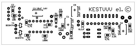
Hard drive indicator circuit
Setting up the indicator comes down to setting its sensitivity using R14.
CPU load indicator
When the hard drive indicator was already made, I began to think about an indicator for something else. The choice fell on the processor load indicator.
During the search, two options were found - through LPT and through COM.
I chose the COM port only because it was not used, unlike LPT. While searching, I found an article by Clear66, in which he talked about connecting a car tachometer to a COM port. I liked this idea the most because there is no need to make special conversion circuits digital values into an analog signal. The PCTach program is used for control (download link is at the end of the article).
But since there was no tachometer at hand at that moment, I had to make homemade version factory After assembly and configuration, the processor load indicator began to show more or less accurately.
But I didn't like it increased speed display of the load level, which was expressed by excessive twitching of the indicator arrow when the processor load was uneven. But this was corrected by adding an additional capacitor in parallel with the microammeter.
View dial indicator I wasn’t happy with it, and I decided to look for an alternative. Ultimately, the indicator became LED, and not a scale of LEDs, but two LEDs directed towards each other different color glow. The load level is displayed by smoothly changing the brightness of the LEDs.
To make the indicator, I used 4-5mm plexiglass and two LEDs: red and blue. A strip measuring 150mm by 15mm is cut out of plexiglass. After this, places for LEDs are cut out along the edges of the strip. The ends and one side of the strip should be sanded with zero-grade sandpaper to a uniform matte finish. This is necessary for uniform dispersion of light. TO back side(which is not sanded) and a strip of foil is glued to the sides of the strip to reflect the rays of the LEDs. When the strip is ready, the LEDs are glued.
Arrangement of LEDs in a strip of plexiglass
When the LEDs are already glued, electrical tape or self-adhesive film is glued to the ends of the strip. This is necessary so that the LEDs shine only in the desired part of the strip.
Blue on top symbolizes cold, i.e. low CPU load. Red below symbolizes heating, i.e. big load. The processor load is proportional to the transition of colors between each other. The wires going to the board and a 68-100 Ohm resistor are fixed at one edge of the strip using hot glue.
To smoothly change the brightness of the LEDs, a PWM signal generation circuit is used. With this control method, the brightness of the LEDs varies depending on the ratio of the time it is lit and the time it is not lit. This way better control voltage in that the brightness of the LEDs changes proportionally to the voltage.
The scheme consists of the following blocks:
voltage driver on DA1.1
Ramp generator on DA2
voltage comparison unit for DA1.2 DA1.3
The resistor divider R4, R3 sets the voltage to 1.2 volts, which is approximately equal to the minimum voltage of the sawtooth pulses DA2. Pulses are taken from the third pin of the computer's COM port. When the input level is high, capacitor C1 is charged through resistor R1 and diode D1. When the input level is low, capacitor C1 is discharged through R2. A voltage proportional to the processor load level is generated at C1. Since the amplitude of this voltage is less than the amplitude of the sawtooth pulses DA2, there is an amplifier on DA1.1 in the circuit. The maximum level of the indicator is adjusted by changing the gain using R6. The R7, C3 chain finally smoothes out the voltage ripple from the amplifier output. PWM is generated by comparing the measured voltage and sawtooth pulses.
DA1.2 generates a direct, and DA1.3 an inverted PWM signal. These two signals are then sent to LEDs, pre-amplified by switches on transistors T3, T4.
Processor indicator circuit

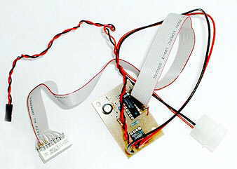
Execution
Since both indicators are located on the front panel, I made a common board for them. On one edge of the board there are two strip-shaped tracks. Two M3 nuts are soldered to these strips. In the front of the housing frame, two 3mm holes are drilled so that they correspond to the distance between the centers of the nuts on the board. Next, two M3 screws are screwed into these nuts on the board, which pass through the holes in the frame.


CPU load indicator with different levels downloads:

One of the most common computer mods is replacing the standard LEDs on the case with some others. However, you must admit that this is too simple. Why not make a kind of VU hard drive loading indicator using several LEDs? Something like a VU-meter on amplifiers.
A suitable diagram was found on the above site:
It's simple. Power supply +5V, on the left in the diagram. At the bottom right, to the outputs of the optocoupler LED (legs 1 and 2), we connect the outputs on the mother, called HDD Led. If you reverse the polarity on this LED, nothing bad will happen, the LEDs will simply not light up. But at the +5V input, it is advisable not to confuse the polarity.
The advantage of such a circuit is that the HDD Led signal from the mother is not used by your circuit directly (the change in the resistance of the emitter-collector junction of the optotransistor in the optocoupler is used). And, therefore, if you connected the mother to the correct outputs of the optocoupler, then no matter how incorrectly your circuit is assembled, it will never damage (read: cover) the mother. :-)
The jumper in the diagram determines the operating mode of the LED scale. If it is closed, then the LEDs light up one after another from right to left (according to the picture), if it is open, then only one LED will always light up, i.e. you get something like a “jumping dot”. Because I didn’t like the last option, so I made the circuit without a jumper (I simply shorted this section).
So, let's look... What we need for this:
- LM3914 itself, in fact, is a microchip that controls LEDs (led bargraph driver chip);
- 4N25 (or 4N26, or 4N28 or TIL111) - optocoupler (optoisolator);
- Electrolytic capacitor: 220 µF at 25V (with a voltage reserve);
- Resistors (one piece each): 3.3KOhm, 10KOhm, 470Ohm, 330Ohm, all 0.25W.
- LEDs for 2.5-3.5V - 10 pcs, cool - multi-colored.
Because I found the diagram on an import site, so first I decided to assemble everything on cardboard and wires to check its functionality, check it out:


For testing purposes, I was too lazy to solder all 10 LEDs, so only five pins from the main device were used. Since I checked it worked, you can skip this step :-).
For ease of connection, you can also stock up on the following components:
- Colored wires (black and red) for connecting to the mother and power supply;
- Molex connector for connecting to a standard power supply; you can buy 2 (male and female for attaching to a wire) and make another coupler if there are no free connectors on the power supply;
- Thin wires, a cable, or a block with screws on a board for connecting LEDs;
- Beds for microcircuits (18 and 6 legs) - highly recommended;
- What you will solder this whole thing on: circuit board, foil PCB/getinax, cardboard (ghetto-mod:-)).


In principle, it can be made more compact, but that was not my task. Don't forget the mounting holes in the board if you need them!
I made the board as follows. Contact ferric chloride, varnish and solvent, I didn’t want to use it, so I glued a board printed on paper in a 1:1 format with an adhesive stick onto the PCB from the foil side (laugh in vain, it [the adhesive stick] is easy to use, provides good adhesion of the paper to the foil and, at the same time, time, the paper can then be easily peeled off without the use of additional tools). I drilled holes in it just like that. I tore the paper off the foil, connected the required holes with a pencil according to the board layout, and cut out the tracks with a knife. The holes for the power wires can be made with a diameter of about 1.5mm if you are going to use standard wires from the power supply (I did so, taking them from an old power supply).
In general, there is nothing complicated here, but you need to very carefully solder the narrow paths going from the microchip to the LEDs, because There are a lot of them and you can’t make them thick. Although I soldered a lot at one time, it was still not very easy... The main thing is that after cutting, thoroughly clean and degrease the board before soldering. The better you clean/degrease, the easier it will be for the tin to stick to the foil and the less chance it will come off the board. It is better to solder immediately after stripping, and all the elements at once, without putting it off until the next day, otherwise, if you solder half of it today and, without treating the board in any way, leave it for a week, then you will have to hemorrhoidally clean the pads again or heat them up more strongly with flux, from which, most likely, the tracks will come unstuck.
Here's what I got:
I decided not to mess with a bunch of LEDs and installed a set of ten LEDs in one housing, connecting it to the board with an 11-wire cable, cutting the cable from the drive accordingly. I soldered the cable directly into the board, but only then did it occur to me that I should have installed a connector there.
I highly recommend using cribs for microcircuits. Firstly, you won’t overheat when soldering onto the board (micrugs are inserted last), and secondly, if a mikrukh is found to have a manufacturing defect (not working, in short), then you can easily change it in the store where you bought it, and the soldered one will be yours will not be replaced.

When you have soldered the whole thing, you can check the functionality as follows:
- When power is turned on, no LED should be lit;
- If you close contacts 4 and 5 of the optocoupler (those that go into the circuit), then all the LEDs should light up (or only the last one, if you assembled a circuit with a break instead of a jumper).
If everything works, you can experiment, for example, with the order of connecting the LEDs, for example, so that the even ones in a row light up first, and then the odd ones, etc.
Analog hard drive loading indicator
For fans of analog technology, we can offer this option:
Those. Instead of a circuit and LEDs, you can connect some existing dial indicator with decent internal resistance, for example, from some kind of tape recorder. Use a potentiometer to set the current limit. We connect to the HDD-Led connector on the mother. Unlike the previous option, here, if you take a device that is too powerful and not very sensitive (with low internal resistance), you can easily damage the motherboard and then you will not have any HDD operation indicator.


