Installation and repair of DVD players BBK DV911/DV311S/DV113
The article discusses the device, circuit diagrams, repair features and typical malfunctions of DVD players BBK DV911/DV311S/DV113
General information
These players support the following formats: DVD-video, VCD 1.0/1.1/2.0, SuperVCD, CD-DA, HDCD, MP3, JPEG, Kodak Picture CD, WinMedia from DVD-R/RW/+R/+RW, CD media -R/RW.
To connect various devices Three types of video signals are generated at the output connectors of DVD players:
composite video signal (PTsTS, interlaced scanning PAL, NTSC) on RCA and SCART outputs);
component video signal YPbPr (progressive scan) on RCA outputs, or on SCART.
separate luminance Y and chrominance C signals at the S-video output.
Sound processing is carried out in PCM-stereo and MP3 formats with a sampling frequency of up to 192 kHz.
The digital audio output signal is generated in DTC format and output through a coaxial connector. Analog stereo audio is output via RCA and SCART connectors.
Design and differences between models
The players are made in a flat metal case. Electrical part consists of four printed circuit boards: power supply (PSU), MPEG decoder and servo control (DSU), front panel with buttons and indicator (UI) and microphone amplifier. In the central part of the case there is a DVD drive, made in a separate case with horizontal loading of discs. The drive housing is mechanically fastened with four screws and electrically connected to the main MPEG decoder board using two cables: flat - for connecting the optical converter (OC) with the board via high frequency(RF), and "twist" - to control the drive motors.
The OP includes two blocks with laser diodes. They operate at wavelengths of 780 nm (for reading CDs) and 650 nm (for reading DVDs). Also installed on the OP body are: a board for turning on and adjusting the DVD laser, a lens with focusing and tracking coils, a block of photoelectric converters (FEC), four of which (ABCD) are used for reading information and focusing control, and two (EF) for monitoring deviation of the beam from the center of the track.
The mechanical part of the drive consists of a loading motor, a tray position switch during loading/unloading of the disk, a mechanism for moving the OP back and forth with a servo motor, a spindle motor and a mechanism for fixing the disk in the working position.
The DSU board includes: a DVD controller based on the MT1379 chip from MediaTek, an amplifier-converter of RF signals of the MT1336 type, a motor control power drive on the BA5954 chip, a CS4340 stereo decoder and audio amplifiers on the 4580 chip.
The front panel contains: control buttons, an operating mode indicator and a Karaoke microphone input. In the DV911SM and DV311S player models, the operating modes are indicated on the display.
The rear panel contains RCA connectors for outputting YPbPr component video, composite PTsTS, L and R stereo audio signals, 5.1 audio signal, a coaxial connector for digital audio output and a SCART connector.
Description of the electrical circuit diagram
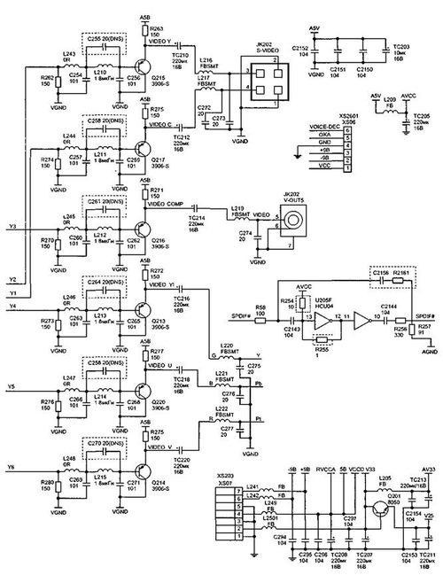
The block diagram of the players is shown in Fig. 1. When the device is turned on, the main components are tested. The position of the limit switches, the serviceability of the laser (lighting), the tracking system motor (moving the optical converter to the beginning of the disk), and the focusing and tracking system are checked. If all mechanisms are working properly and the supply voltage is normal, the device is ready for operation. The tracking system motor and spindle motor (disk rotation), focusing and tracking coils are controlled by the U302 (BA5954) microcircuit. Signals A, B, C, D, E, F taken from the solar cell are processed in the RF amplifier microcircuit U301 (MT1336), which is connected to the OP via the DV34 interface. Analysis of incoming information, digital and analog processing of video signals and digital processing of audio signals, generation of control signals and voltages for the servo drive is performed by the DVD controller - chip U201 (MT1379). Dynamic synchronous memory chips SDRAM U203, U204, flash memory U214 and EEPROM U202 are connected to it. The image signal is taken directly from the controller pins, and the stereo sound signal is generated by the U207 (CS4340) processor.
The power supply generates a voltage of 5 V to power the DVD drive motors, 3.3 V to power the DVD controller, RF amplifier and memory chip, and a bipolar voltage of ±9 V to power the outputsound amplifiers.
Let's take a closer look at the operation of individual player components.
power unit
The power supply is made according to the scheme pulse converter. It uses a U501 controller (VIPER22) with a built-in MOSFET transistor, using a minimum number of external elements (Fig. 2). A constant voltage of 310 V is generated on the capacitor TC501, which is supplied to the pin. 5, 6, 7, 8 controllers. Power supply to the controller in operating mode is provided by the D506, R505 chain. The power supply operating modes are controlled by the U502 optocoupler. At the power supply output, non-stabilized voltages of +5, ±9 and 3.3 V are formed. The DVD controller, OP, flash memory and RAM chips, and RF amplifier are powered by a voltage of 3.3 V. A voltage of 5 V powers video signal amplifiers, control buttons and a remote control receiver, motor control circuits, etc. A voltage of ±9 V powers the final audio amplifiers. Voltage stabilization is carried out via the 3.3 V bus using a circuit feedback from elements U502 and U503.
Path for processing the output signal of the optical converter
The basis of the tract is the U301 microcircuit of the MT1336 type from MEDIATEK (Fig. 3). It is made in a 128-pin package and is powered by a voltage of 3.3 V (pins 64, 67, 69,109 for the processing section and 54, 37 for the output section).
The input signals for the U301 chip are:
signals from four photodetectors (ABC D), read from the surface of the laser disk (pin 97-100), from which a data stream with video and audio information is formed (A+B+C+D);
inverted signals A, B, C, D (pin 101-104) from which the focus error signal (A+B) - (C+D) is formed; signals from photodetectors E and F (pins 115, 116), from which an error signal for following the center of the track and tracking is generated;
signals OR+, OR- (pins 71 and 72), proportional to the control voltages of the spindle (motor to ensure control of its rotation speed); signal from the MD11 monitor diode with OP (pin 124) - to ensure automatic control DVD laser diode current; PWM signal PWMOUT2 (pin 61) from the MT1379 decoder - to control the operating modes of the DVD drive;
the reset signal URST (pin 60) is generated using the U205 (HCU04) chip; interface signals SDATA, SDEN, SCLK (pins 56, 58 and 59) for data exchange with the DVD controller;
signals from the limit switch of the tray position (pins 47 and 48) - in closed (TRIN) and open (TROUT) states;
signal of the initial position of the OP (at the beginning of the disk) - LIMIT (pin 49).
Rice. 1. Block diagram of DVD players
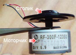
Fig. 2. Power supply
The U301 chip generates the following output signals:
with pin 125 and 126, the voltages LD01, LD02 are removed to turn on the DVD or CD laser diodes;
with pin 52 the PWM signal IOA is removed - for automatic adjustment DVD laser current;
with pin 6 and 7, antiphase high-frequency signals RFON, RFOP, used by the DVD controller to generate digital audio and image signals, are removed;
with pin 18, 20 and 21, the FEO focusing error signals, the beam deviation from the center of the CSO track and the TEO tracking signals are removed, which are sent to the decoder to generate a control signal for the focusing and tracking coils;
on pin 19 the envelope of the RF signal RFL is formed, which is used to control and ensure automatic adjustment of the beam current;
with pin 70, the reference voltage OPO for acceleration or braking of the spindle motor is removed. The voltage difference in the form of the ADIN signal is used to control its rotation speed;
on pin 53, the TRCLOSE disk loading signal is generated, and at pin. 50 - signal to turn on the standby mode STBY (supplied to the power drive to suspend the operation of the engines when there is no disk in the drive);
on pin 15, 16 and 17, reference voltages of 1.4 V, 2 V and 2.8 V are formed to power the tracking system motors, tracking and focusing coils.
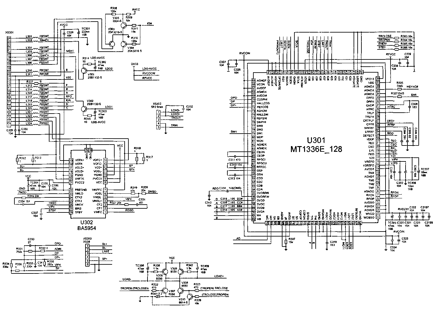
Fig. 3. RF signal processing path (MT1366 microcircuit). DVD Driver (Click on images to view larger version)
Decoding and servo control circuits
The functions of MPEG-1/2 and JPEG decoders, servo controller, television video processor, digital audio decoder, button control microcontroller and remote control are performed by the U201 chip (MT1379E_216) (Fig. 4). It has a sectional structure. Let's take a closer look at the description of these sections.
Servo control section
To control the motors and optical converter, the U201 chip receives the following signals:
signal tracking the trajectory of the beam in the center of the CSO track (pin 204);
focus error signal FEO (pin 205);
tracking error signal TEO (pin 203);
voltage proportional to the instantaneous rotation speed of the spindle motor ADIN (pin 200);
antiphase RF signals RFIN, RFIP, read from the disk (pin 215, 216).
After digital processing of the received data, the MPEG decoder block generates the following output signals to control the DVD drive motors:
on pin 12 and 13, control signals are generated for the focusing and tracking coils FOSO and TRSO, which are supplied to the power drive;
with pin 14 the TROPEN signal is removed to open the tray;
with pin 16, the PWM signal PWMOUT2 for automatic laser current adjustment is removed;
with pin 18, the PWM signal DMSO is removed - to turn on and control the tracking motor (moving the OP along the disk tracks);
with pin 19, the PWM signal FMSO is removed - to turn on and control the spindle motor.
Microcontroller section
It is based on a RISC microprocessor included in the MT1379E_216 microcircuit (Fig. 4). It has a 16-bit I/O interface (with pins 105-124 - address buses, and with pins 75-86 and 93-101 - data buses) with two SDRAM memory banks U203, U204, which are used for temporary data storage , providing the necessary speed and quality of decoding.
On the pin. 22-27, 40-53 (address bus) and 31-39 (data bus) a 16-bit interface is organized with the exchange of Flash memory U214 (Fig. 5). It stores the initial data for controlling servo motors, implements an algorithm for the interaction of elements in the formation of sound and image, digital and analog signal processing, and the OSD menu.
Non-volatile memory (EEPROM or EEPROM) U202 is connected to the microcontroller via the PC bus (pins 65 and 67). Exchange with this type of memory occurs when the device is turned on and off and ensures that the player is tested, after which control is transferred to the program stored in Flash memory. In addition, this chip stores user settings and regional protection (zone) data.
Video and audio signal processing section
In the video signal processing section, the frames of the digital data stream stored in RAM are decoded and encoded in 4:2:2 format.
The composite video signal PCTS (interlaced scanning) is generated in the PAL and NTSC color systems and is removed from the pin. 168 and through the operational amplifier Q216 goes to the RCA connector. On the pin. 170, 172, 173 components of the YPbPc (progressive scan) component video signal are formed, which are supplied to the rear panel RCA connector through amplifiers Q213, Q220, Q214. When the signal is switched by software, analog RGB signals are generated on the same pins, which are output through the SCART connector. From pin. 164 and 166, the brightness and chrominance signals Y and C are captured, which are output through the S-VIDEO connector.
The audio decoder supports digital, 2-channel stereo and surround sound formats in AC-3 5.1 format. It uses a standard input interface l 2 C and a digital output output S/PDIF (pin 153). From pin. 183 (PSLRCK), 184 (PSBCLK), 181 (PSDATO), 180 (PMCLK) and 151 (ACLK) of U201 chips capture clock signals and data that are used to generate an analog stereo signal in an external stereo processor.
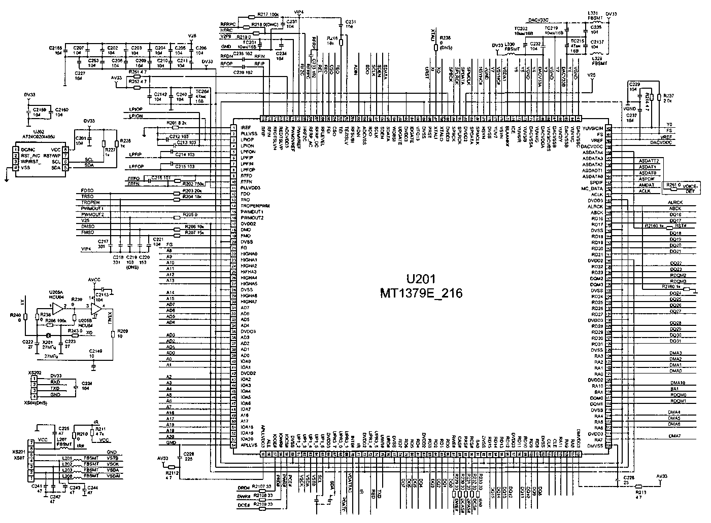
Rice. 4. MPEG-1/2 and JPEG decoder, servo controller, television video processor, digital audio decoder and control microcontroller (MT1379 chip) (Click on the images to view a larger version)
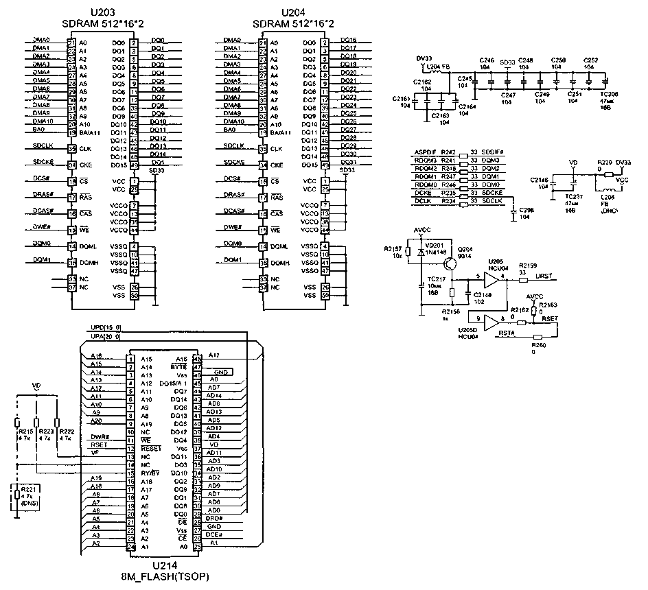
Rice. 5. Flash and SDRAM Memory (Click on the images to view a larger version)
To pin. 152 connects the microphone input for karaoke mode. On the pin. 158 a RESET signal is generated for the stereo processor. Pin status 157 (log. “1” or “O”) determines the presence of a microphone at the microphone input.
Control and status section
To pin. 186 and 187 U201 a quartz oscillator is connected using elements U205 and X201, which stabilizes the frequency internal generator 27 MHz. On the pin. 188 the RESET voltage is set. The control protocol for the OP and the RF amplifier is implemented using a 3-wire SPI bus - pin. 195, 196, 197 (SDATA, SDEN, SCLK).
To pin. 71 is connected to the output of the IR receiver of the remote control, and to pin. 62, 63 and 64 (DST, DCK, DAT) - front panel keyboard matrix. To pin. 73 RXD and 74 TXD, an external flash memory programmer is connected, the signals of which are input through the XS202 connector (for the programming procedure, see below).
DVD drive driver
The DVD drive motors, focusing and tracking coils are controlled by the U302 (BA5954) chip (Fig. 3). It includes two coil drive channels and two motor control channels. The microcircuit is powered by a voltage of 5 V (pins 8, 9 and 21) and controls the spindle motor (pins 11, 12), the servo motor (pins 17 and 18). The power drive for the focusing coil is pin-type. 13 and 14, and for tracking - at 15 and 16.
On the pin. 26 receives the TRSO signal from the MPEG decoder to control the tracking coil, and to pin. 1 - FOSO signal for turning on the focusing coil. On the pin. 5 the PWM signal DMSO is received to turn on and control the servo motor, and to pin. 23 - FMSO signal for turning on and controlling the speed of the spindle motor. On the pin. 4, a reference voltage of 1.4 V is supplied to adjust the position of the laser beam in the center of the track by adjusting the rotation speed of the tracking motor.
The loading circuit is made in the form of a separate circuit using transistors V306, V307, V308, V309. The TROPEN tray opening voltage comes from the DVD controller, and the closing voltage (TRCLOUSE) comes from the RF amplifier chip. The loading/unloading signal is directly removed from the collectors of transistors V306 and V309.
Sound path
The analog audio signal is generated by the U207 (CS4340) chip (Fig. 6). It receives the following signals:
RESET - initial reset (pin 1);
SDATAO - data (pin 2);
SBCLK - clock signal for controlling the audio channel interface (pin 3);
SLRCK - signal for switching the right and left channels (pin 4);
SACLK - reference frequency signal for stereo decoder operation (pin 5);
NUTEC - pause signal (pin 16).
The microcircuit is powered by a voltage of 5 V (pin 14). Analog audio signals of the right and left channels are removed from the pin. 12 and 15 U207. From here, the signals through op-amp U219 go to the RCA connectors (JK201).
Keys on transistors Q205, Q206 and Q219, controlled by the MUTE-1 signal (forms a node on transistors Q211, Q212, Q218, Q219) are used to block sound. Op amp U220 generates an audio signal for the subwoofer.
Typical faults of DVD players and methods for eliminating them
The player does not turn on, the indicator on the front panel does not light up
First, check the serviceability of the power supply and, first of all, the presence of a voltage of 5 V at its output (if this voltage is absent, check the serviceability of the diode D510 and capacitors TC505, TC506, TC510).
If the power supply is completely inoperative, check its input circuits and the PWM converter. First, check the presence of a constant voltage of 310 V on the capacitor TC501, and, in its absence, check the serviceability of fuse F501 and diodes D501-D504. If there is voltage, but it is too low, replace the capacitor TC501. If fuse F501 is faulty, check for short circuit diode bridge D501-D504, capacitor TC501 (for leakage) and controller U501. If the voltage at the pin. 5-8 of the U501 microcircuit is 310 V, but there are no trigger pulses (monitored by an oscilloscope at pins D), check elements D506, TC502, R505, U502. If all of the above elements are in working order, replace the U501 chip.
The player does not switch to operating mode and does not respond to control buttons
Check the voltage of 3.3 V and, if it is not there, elements D509, D513, TC510 (Fig. 2). If the voltages of 3.3 and 9 V are too low, check the feedback circuit elements U503, C5156 R508, R509 and U502. If there is no voltage at the pin. 3, 4 U501, replace the controller, if it is present, replace the optocoupler U502. It should be noted that if the stabilizer U503 malfunctions, the voltage at the pin. 1 and 2 optocouplers will be the same. If the voltage at the pin. 1 stabilizer U503 is 2.5 V, and the deviation of this voltage exceeds 0.15 V, it is replaced. Using an oscilloscope, check the signal at the pin. 5-8 U301. If the pulse frequency at this pin differs from 100 kHz, the microcircuit is replaced.
If the power supply is working, check the supply voltage of 3.3 V at the pin. 55 of the U201 chip (Fig. 4), as well as the RESET voltage (3.3 V) on the pin. 188 of the same microcircuit. If the RESET voltage is zero, check the circuit for its formation and the serviceability of the driver U205, transistor Q204 and diode VD201 (Fig. 4). Then they check for the presence of a 27 MHz clock signal on the pin. 187 and 186 U201. If it is absent, check the generator on elements U205 A/B, X201 and the DVD controller U201 (by replacement). Before replacing quartz, all elements of the quartz oscillator circuit are soldered, special attention is paid to the serviceability of capacitors C222 and C223 (they can be unsoldered for a while, and if the device “starts” at the same time, they are replaced).
Check the operating mode of the EEPROM U202 memory chip, while the voltage on the pin. 8, 5 and 6 should be 3.3 V, and on pin. 1, 2, 3, 4 and 7 are equal to zero. If on pin. 7, connected to pin. 75 U201, there is a voltage of 3.3 V, then you can temporarily disconnect this pin from the bus and connect it to the case. If the device “starts” at the same time, the DVD controller is faulty. If the power supply to the EEPROM chip is normal and no exchange occurs between it and U201 (pins 65 and 67) when the player is turned on, then replace the memory chip. When replacing, there is no need to have firmware for this chip. In place of the faulty memory, a clean one is installed, and when the player is first turned on to the network, the microprocessor in the DVD controller itself “flashes” it. For full confidence On the programmer, the hexadecimal code FF is written to all cells of the new memory. If all the above measures fail, replace the U201 controller.
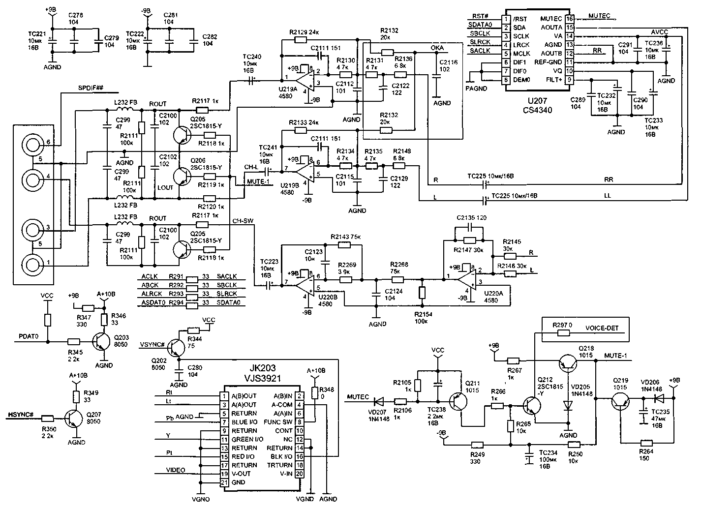
Rice. 6. Audio signal decoder CS4340. RCA and SCART connectors (Click on images to view larger version)
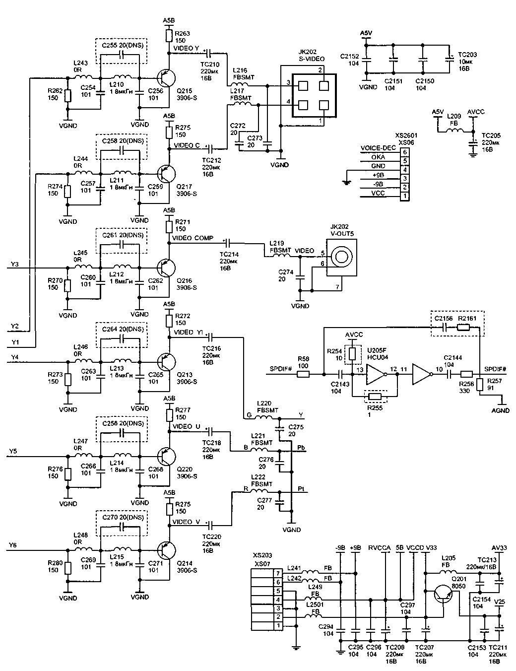
Rice. 7. S-VIDEO, YPbPr connectors (Click on the images to view a larger version)
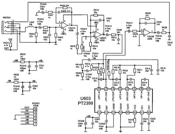
Rice. 8. Echo processor RT2399. IR receiver HS0038A2
Tray won't open
Check the 5 V voltage on pin 4 of connector XS203 of the DSU board. If it is underestimated, then check the capacitors TC505, TC506 and the diode D510 in the power supply (D510 is a Schottky diode (therefore it needs to be replaced with a similar one). If the voltages are too low, 5 and 9 V, check (and, if necessary, replace) the stabilizer U503 (LM431, analogue - TL431), as well as optocoupler U502 (2501, can be replaced with LM817).
If all voltages are normal, proceed to checking the DVD drive. Check the serviceability of the loading-unloading mode switching bar, the cleanliness and condition of the gear teeth. They also check the functioning of the limit switch (Fig. 9), for which they push the tray into the manual tray, rotating the tray extension gear, and remove it by bending the locking latches. In the working position, the shift lever must be located between the guides of the shift bar. Check for a short circuit between contacts 3 and 5 with 4 on the XS302 connector (Fig. 3) in the extreme positions of the switch lever.
Check the serviceability of the loading motor. For this purpose, with the motor disconnected from the circuit, a voltage of 5 V is applied to its terminals and the rotation of the axis is controlled. If the axis does not rotate (or rotates with difficulty), you can try to restore the serviceability of the engine by cleaning it from contaminants. To do this, place the motor housing in alcohol and apply voltage to its terminals - in this way they try to rinse it. After washing, the engine is dried compressed air. If the engine cannot be restored in this way, it is replaced. In this case, you can replace the engine with a similar one from any faulty CD or DVD drive. It is advisable to select a motor with the same winding resistance (about 30 Ohms).
If the engine is working properly, check its control circuits. They control the change in voltage using the OPEN command - while on the pin. 14 U201 (Fig. 4) should appear high level(3 V), and when closing the tray - a high level on the pin. 53 U301 (Fig. 3). If these signals are missing, replace the corresponding microcircuit. Then transistors V306, V307, V308, V309 are checked.
Rice. 8. (end)
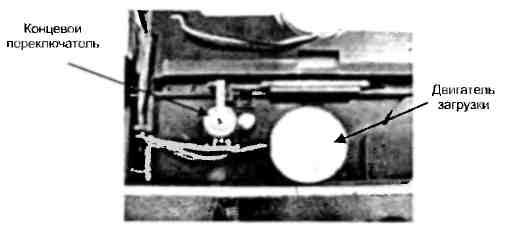
Rice. 9. Limit switch
Disc loads but can't be read
Monitor the operation of the drive and the OP with the housing cover and the plastic disk holder strip removed. Without installing the disc in the tray, press the OPEN/CLOUSE button, the tray should be in the working position, the OP will move to the beginning, the laser will light up, the focusing and tracking mechanism will turn on and the spindle motor will make several revolutions.
The following cases may occur:
The disk loads and spins, but the laser does not light up
You can determine the serviceability of a DVD laser visually by its bright red glow (650 nm). The serviceability of a CD laser is more difficult to determine, since its radiation (780 nm) is in the invisible part of the spectrum. Its glow can be checked using a digital video or photo camera. In shooting mode, the glow of the CD laser will be visible on the LCD display. If there is no laser glow or it is weak, check the cleanliness and transparency of the lens. Allowed light touch dust on the lens. It is not recommended to use a cleaning disc to clean the lens, as its effectiveness is low (dust is not completely removed from the lens). To clean the lens, it is recommended to use glass cleaner (for example, "Mr. Muscle") or a soap solution. Using a cambric cloth soaked in this solution, lightly touching it, wipe the lens in a circular motion from the center to the edge.
If the lens is clean, but there is no laser light, check the voltage of 3.3 V in the power supply. If the voltage differs from the specified one, then repair of the power supply is necessary (see paragraph “The player does not switch to operating mode”). Check the laser supply voltage (3.3 V) on pins 19 and 23 of the XS301 connector, as well as its formation unit on elements V301, V302. The voltage at the collectors of the transistors should be equal to 2.2 V (when the DVD laser is turned on), and 2 V (when the CD laser is turned on). If there are no turn-on voltages LD01, LD02 on the bases of transistors V301, V302, check their circuits from the pin. 125 and 126 U301 chips. If these voltages are absent when loading the disk, then check and replace U301. When the lasers glow weakly, their current can be adjusted variable resistors installed on the OP board. The adjustment should be made with the player turned off using a thin screwdriver. They also check the quality of the wiring of the protective jumpers (on a new OP they are sealed and are removed directly when installing it in the device). If the above actions do not eliminate the defect, check the serviceability of the laser diodes themselves. This can be done in two ways, after first removing the laser head from the guides.
1st method. An external regulated DC voltage source supplies a voltage of 2 V through a 100 Ohm quenching resistor to the terminals of the corresponding laser diode. If the diode does not light up at a voltage of 3 V, it is most likely faulty. Voltage is applied to the right contact of the laser unit relative to the central point (the output of the monitor diode is on the left), while the “+” of the source is connected to the central contact, and “-” to the right one.
2nd method. From generator rectangular pulses a “meander” signal with a swing of no more than 1.5 V and a frequency of 1 kHz is supplied to the laser. It is strictly forbidden to check the serviceability of laser diodes with analog testers, since they measuring current at low resistances it can damage the diodes. Faulty laser diodes are replaced complete with control circuits. You can try replacing the diodes themselves from faulty computer drives. In this case, replacing the CD diode does not cause any difficulties. It is not so easy to replace the DVD diode - it is installed in the control board.
The disk is not readable and rotates intermittently
Check the 5 V voltage at the power supply output. If it is low, see "Tray does not open." When the supply voltage is normal, the power drive microcircuit (motor driver) checks the serviceability of the spindle motor itself in the same way as the loading motor. If the disk rotates intermittently, contamination may occur on the collector (even to the point of rust). It can be cleaned. If on Idling Extraneous noise is heard from the engine, it is replaced. Check the supply voltage on pins 5 and 6 of the XS303 connector, which should reach 2 V at maximum engine speed. The lack of rotation of the disk or its intermittent rotation may be due to a malfunction of the laser diodes. In this case, they are checked (see above). They also check the flexible flat cable connecting the optical converter to the main board for mechanical damage, as well as distortions when installed in the connector. A malfunction of the spindle motor (lack of full contact of the brushes with the commutator) can also be determined by the strong heating of the U302 driver.
There is no up and down movement of the lens
Most likely the focusing system is not working. The focusing coil is tested using the FOSO command (pin 1 of the U302 chip), which comes from the DVD controller (pin 12 of the U201 chip). If during testing the voltage between pins. 14 and 13 U302 reaches 4 V, then U201 is OK. If this does not happen, check for the presence of an alternating signal FEO on the pin. 18 U301 chips. If it is absent, while the laser diode is glowing, check the RF signal at the pin. 6 and 7 of the same microcircuit. If the RF signal appears, but the FEO does not, then replace the U302 chip.
Check the serviceability of the focusing coil; its resistance should be about 20 Ohms. Apply a voltage of 2.5...3 V to the focusing coil terminals (the two rightmost contacts on the OP board), and the lens should move. If this does not happen, solder the focusing coil connection contacts. If the focusing coil is faulty, replace the OP. If the lens does not move vertically when the coil and RF amplifier are in good working order, check the voltage at the pin with an oscilloscope. 13 and 14 U302. It should be 4 V and will change within ±0.2 V as the lens moves. If this does not happen, replace U302.
The disk is in the device and cannot be ejected
First of all, you need to remove the disc from the tray. For this they remove top cover player, remove the top plastic fixing bar (by unscrewing two screws) and remove the disc. Without installing the bar in place, check the operation of the loading mechanism by pressing the OPEN/CLOUSE button. If at the same time the tray starts to move, but stops, check the condition of the drive gear and the lifting/lowering bar of the OP (see Fig. 10), for which they remove the tray (bend the plastic fasteners) and check the condition of the teeth. Having replaced the faulty parts, install the tray in place; to do this, turn the loading mechanism gear by hand until the OP takes the lower position. Then insert the tray into the grooves of the drive and push it by hand, bending it slightly until the first tooth of the tray gear line connects with the loading drive gear. The limit switch lever must be located between the outermost projections of the OP lifting bar.
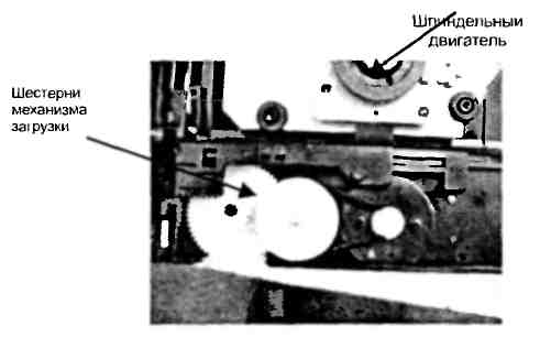
Rice. 10. Loading mechanism and spindle motor
If, when loading the disk again, it does not unload, check the serviceability of the limit switch (see Fig. 9), the receipt of the OPEN signal from the pin. 14 U201 and, if it is missing, check the serviceability of the tray control button on the front panel. If all of the above steps do not produce results, replace the DVDU201 controller.
When loading a disc, the lens moves erratically and may even damage the disc.
The disc loads, but cannot be read, the message "No disc" appears on the TV screen
If there are no problems with the DVD drive (as discussed above), check for the presence of a total RFO signal on pin 8 of the XS301 connector or on each line A, B, C, D (pins 5, 6 and 9, 10 of the XS301 connector). If the laser diode lights up, but there is no signal or it is too small (the signal swing should reach 1.5 V), adjust the current level of the laser diode using adjusting resistors installed on the OP. If the total signal cannot be increased, then the photodetector is faulty. In this case, replace the OP assembly.
If the RFO signal is normal, and the pin. 6 and 7 U301 there are no RFON and RFOP signals, then the problem is related to a malfunction of the high-frequency amplifier. First of all, check for the presence of a voltage of 3.3 V and the URST signal on the pin. 60. If 3.3 V power appears when the XS203 connector is disconnected, check the 3.3 V stabilizer and consumers, sequentially disconnecting the load: AV33 bus (power supply U201), DV33 bus (power supply U301 RF amplifier), faulty elements are replaced. Check the URST signal generation circuit - operational amplifier U205 and capacitor C214. Also check the voltage at the pin. 59 and 56 U301. If it is significantly lower than 3.3 V, check the I 2 C bus to the pin. 197 and 195 U201. A low voltage level indicates a malfunction of one of the microcircuits. They determine which of them is faulty by breaking the I 2 C bus. If the voltage at the pin. 197 and 195 U201 will increase to 3.3 V, then U301 is faulty. Otherwise - U201.
PLAY mode does not turn on; when loading a disc, the OP moves not to the beginning of the disc, but to the end, or does not move at all
Check the serviceability of the driver U302 (BA5954) and the voltage level at its pin. 8, 9 and 21 (should be 5V). If the voltages are too low and the microcircuit gets very hot, it should be replaced. Analogues of this microcircuit are D5954, AD5954 or AM5954.
Check the serviceability of the gears and guide pins along which the OP moves (Fig. 11). Check the smooth movement of the OP along the guides. If the OP moves jerkily, wipe the guide axes and lubricate them with special silicone grease. They check the serviceability of the tracking system motor, measure the resistance of its windings with a tester (should be about 20 Ohms). Connect the motor to a 5 V DC voltage source, changing the polarity. In this case, the engine should rotate evenly in both directions. Otherwise, it is replaced. If the engine is faulty, check its control circuit (driver). When moving the motor, the voltage swing across the pin. 17 and 18 U302 must be at least 100 mV (with a supply voltage of 2.5 V). If this voltage is too low, the microcircuit is replaced. If the voltage is zero, check the arrival of the FMSO signal at the pin. 23 U302 from the DVD controller (pin 19). The absence of this signal from the controller may indicate either a malfunction of the controller itself (for example, its overheating) or problems with focusing.
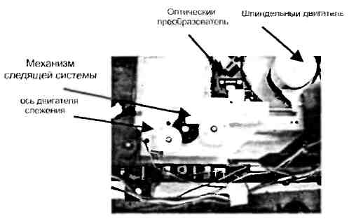
Rice. 11. Tracking system mechanism
When you turn on the device and load a disc, the indicator starts blinking or turns off completely, messages appear on the TV screen that do not correspond to the actions being performed
If such a defect appears when there is no disk in the tray, check the serviceability of the indicator board of the connecting cable with the main board and the quality of soldering of the indicator itself. This kind of malfunction can be detected by tapping the board (due to the constant mechanical impact on the board, soldering failures often occur.
Incomprehensible behavior of the indicator or lack of information on the TV screen may be due to a faulty Flash memory U214. First of all, check its power supply of 3.3 V (at pin 13-15). If it is absent or low, and there is 3.3 V on resistors R215, R222, R223, then the microcircuit is faulty and needs to be replaced. After replacing the flash memory, it must be flashed (see section "Flash memory chip firmware").
DVDs are not readable
First of all, check the serviceability of the DVD laser diode (see fault above). The signal from the generator must be supplied not directly to the laser diode, but to a capacitor installed at the input of the DVD diode current control board. If the laser diode lights up, but the DVDs are not readable, you can try to adjust the diode current with an adjusting resistor with index “D” (in fact, this resistor regulates the sensitivity of the monitor diode). It is safer to make adjustments with the power turned off. The final control of the laser diode current is carried out by the swing of the RF signal controlled at the pin. 6 and 7 U301 (in DVD playback mode).
If the DVD laser diode lights up during testing, but the discs are not readable, check the presence of the LD01 signal based on transistor V302, as well as the serviceability of the transistor itself. If there is no laser turn-on voltage (2.2 V), then replace the U301 chip.
If the voltage swing level at the pin. 6 and 7 are significantly below 2 V, and the signals on the pin. 97-100 are also underestimated, replacing OP.
CDs can't be read
To test this problem, burn a disc in VCD format. Check the functionality of the CD laser diode (see above). The performance of the CD laser diode can be checked using a digital tester (in this case, an analog device cannot be used). The sensitivity adjustment resistor for the CD monitor diode is installed on the board and is marked with the letter “C”. If, after trying to read a CD, voltage does not appear at the base of transistor V301, check the transistor and microcircuit U301.
The player does not respond to control panel buttons
Check the buttons and the presence of a voltage of 3.3 V on the pin. 61, 62, 63, 64 U201. For a player without a front panel display, this check is sufficient. If the voltages are too low, check and replace the DVD controller (U201). If the device has a display, disconnect connector XS07. When a voltage of 3.3 V appears, check the display controller - the RTS 16311 microcircuit. If the power indicator LED lights up, check the button control matrix on the pin. 10-13. Gating pulses must be present at these pins. If they are absent and the voltage level is low, replace the RT16311 controller.
There is no service information on the display or TV screen, although the player responds to control buttons
For players without a display, check the functionality of the DVD controller. Check the EEPROM U202 memory chip. If the voltage at the pin. 5 and 6 (at a voltage of 3.3 V on pin 8) are too low, then the microcircuit should be replaced or rewritten.
No picture or sound
Check the functionality of the DVD controller. Monitor the presence of signals on the pin. 168 (PTsTS, interlaced scanning), pin. 170 (luminance signal Y, progressive scan) and pin. 181 (SPDATA, digital audio). If they are not there, check the dynamic memory chips U203, U204, as well as the presence of 3.3 V power on the pin. 1, 7, 13, 25, 38 and 44. The serviceability of these microcircuits can be assessed by measuring the voltage at the pin. 2-12 and 39-49 (data exchange buses with the DVD controller). At in good condition buses, a high level is set on them. Since the simultaneous failure of two SDRAM chips is unlikely, if any of them is suspected, it is simply excluded from the circuit (via the power bus). If the player's performance is restored, the disabled chip is replaced.
The lack of picture and sound may be due to a faulty flash memory. For information about its replacement, installation and firmware, see “Flash memory firmware”.
There is no image signal at the VIDEO OUT connector (located on the rear panel of the player), there is sound
Probably, during the last playback, progressive scan was turned on (the signal labeled YPbPr in the menu). This can be verified by monitoring the brightness signal at the rear panel "Y" connector using an oscilloscope. If there is a brightness signal, then progressive scan is enabled. To exit progressive scan mode, proceed as follows. Connect the Y signal output to the TV’s AV VIDEO IN video input. If a distorted splash screen image appears, enter the menu and select a “composite” signal (CVC or PCTS logo) in the video output selection settings. Not all TVs (with the exception of LCD TVs and monitors) allow you to reproduce the YPbPr component signal, since modern TVs If the phase of the horizontal pulses fails, the RGB signal outputs are closed. Therefore, according to the second method, connect a cable with coaxial output Y and C, contact Y is connected to the video input of the TV and in the image that appears, enter the menu. If previous attempts do not succeed, reflash the EEPROM U202.
The player turns on, but the indication on the TV screen does not appear immediately
Check for the presence of a voltage of 3.3 V on the pin. 8, 5 and 6 U202. If it is below this value, disconnect the power connector from the DSU board and, if the voltage is restored to normal level, check the 3.3 V power bus on this board (most often, a voltage drop is caused by a malfunction). If the voltage remains low, check and repair the power supply.
The cause of such a defect may also be a malfunction of the DVD drive or its control. You can determine the defective element by touching the U302 driver with your hand. If the microcircuit gets very hot, check it, as well as the drive motors (especially the spindle motor). Connect to pin. 11 and 12 U302 serviceable motor (you can use a loading motor) or a 6 W incandescent lamp. If the amplifier does not heat up and the motor spins normally, replace the spindle motor. Otherwise, replace U302.
No sound, picture ok
Check for audio signals at the RCA output connectors (L or R). If they are absent, check transistors Q205, Q206 and amplifier U219. The check can be performed as follows: with the TV connected, touch the pin. 2, 6 U219. If the background alternating current will be absent in the dynamic heads, check the keys on transistors Q205, Q206 (first of all, control the voltage of -0.5 V at their bases). If it is above zero, check the MUTE1 voltage generation circuit on elements Q218, Q219, VD205, as well as the external microphone connection contacts (must be closed).
Check the power supply of the stereo processor U207 (5 V on pin 14), as well as the presence of a voltage of 3 V on pin. 1 U207. The last voltage comes from op amp U205 after the turntable is turned on. If the voltage is zero, check the DVD controller (pin 158). Low voltage at pin. 158 U201 may be due to either a malfunction of the controller itself or a defect in the Flash memory firmware. Check the receipt of audio data (pulse-modulated signal) from the DVD controller via the SDATA bus. If they are not present, then the malfunction is related (as in the previous case) to the controller and flash memory. The same conclusion is made in the absence of synchronization signals SCLK, MCLK. If the input signals are normal, replace U207.
Sound distortion
First you need to find out that the problem is not related to the TV audio channel. Then transistors Q205, Q206, MUTE1 voltage, as well as capacitors C2111 and C2114 are checked for leakage. Monitor the voltages ±9 V and, if one of them is missing, check the power supply.
MIC is not working
They check the microphone itself by connecting it to a known-good device. Check the voltage at the pin. 4 and 8 U601 (should be -9 and +9 V respectively). If the voltage -9 V is much higher than normal, replace the ZD502 zener diode. If, when installing a new zener diode, the voltage decreases significantly, but does not reach -9 V, replace the U601 chip.
If the signal from the microphone is received at the pin. 16 U603, but there is none at the output (pin 15), check the voltage at pin. 2, which should be 2.5 V. If it is very low or equal to zero, replace this microcircuit. Capacitors C614, C622 and C623 are also checked.
Flash memory chip firmware
There are several ways to initially write (firmware) or rewrite a Flash memory chip. On the VVK technical support website, a Flash memory firmware file is posted for each player model. In order to write a new microcircuit, you must first write the firmware file to a blank CD using the NERO program in the data disk creation mode. Then insert the disk with the firmware into the player and load it. Press the PLAY button and download the update program, the message “File is being copied” should appear on the screen. After this, the tray extends automatically, and the update disc is no longer needed. Then the software update is performed automatically. During the firmware process, you cannot press any buttons on the panel or remote control until the tray on the player closes. After this, we can assume that the Flash memory is flashed correctly.
The second method requires a programmer. In this case, you can use the MEDIATEK programmer based on the MAX232 chip (Fig. 12). The main board of the player has a 4-pin service connector XS202 (signals DV33, TXD, RXD, GND), and the programmer is connected to it. You can make the board yourself (its circuit differs little from DATA cables cell phones). The program for working with this programmer mtktoolv3152_415.exe can be downloaded from the manufacturer’s website. Using this method is only possible if you have a firmware file with the extension .bin or .her. For stable operation of this circuit, it is necessary to use an external power source. The supply voltage can be increased from 3.3 to 5 V, and the firmware speed will increase noticeably.
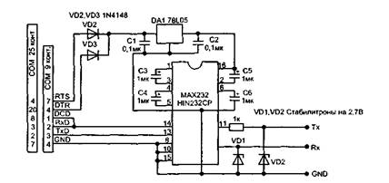
Rice. 12. MEDIATEK programmer based on the MAX232 chip
If there is a need to change the DVD zoning, proceed in the following way. When the player is turned on, enter the “SETUP” menu, sequentially press the number buttons “1-3-5-7” on the control panel (this enters the service mode of the player), then enter the EEPROM 24C02 programming menu. IN additional window menu, select the "Version" item and in the 5th line find the number of the zone used by this player. A player of this type is multi-zone if the “O” zone is in this item.
Installing a new EEPROM memory chip
The new microcircuit must be “clean” or the hexadecimal FF code must be written in the memory cells. After installing the memory chip, the DVD controller itself “registers” its contents the first time it is turned on. If you cannot flash the EEPROM chip in this way, you need to use the firmware by reading the data with the programmer from a working device. Since these devices use a microcircuit in an SMD package, it is more convenient to flash it without removing it from the board. In this case, the SDA and SCL buses and the common wire of the programmer are connected to the corresponding pins of the microcircuit (pins 5, 6 and 7), and the processor reference supply voltage (which is connected to pin 8) is connected to pin. 10 DVD controller MT1379. Turn on the programmer after the DVD logo appears.
The player does not turn on, the indicator on the front panel does not light up
First, check the serviceability of the power supply and, first of all, the presence of a voltage of 5 V at its output (if this voltage is absent, check the serviceability of the diode D510 and capacitors TC505, TC506, TC510).
If the power supply is completely inoperative, check its input circuits and the PWM converter. First, check the presence of a constant voltage of 310 V on the capacitor TC501, and, in its absence, check the serviceability of fuse F501 and diodes D501-D504. If there is voltage, but it is too low, replace the capacitor TC501. If fuse F501 is faulty, before replacing it, check the diode bridge D501-D504, capacitor TC501 (for leakage) and controller U501 for a short circuit. If the voltage at the pin. 5-8 of the U501 microcircuit is 310 V, but there are no trigger pulses (monitored by an oscilloscope at pins D), check elements D506, TC502, R505, U502. If all of the above elements are in working order, replace the U501 chip.
The player does not switch to operating mode and does not respond to control buttons
Check the voltage of 3.3 V and, if it is not there, elements D509, D513, TC510 (Fig. 2). If the voltages of 3.3 and 9 V are too low, check the feedback circuit elements U503, C5156 R508, R509 and U502. If there is no voltage at the pin. 3, 4 U501, replace the controller, if it is present, replace the optocoupler U502. It should be noted that if the stabilizer U503 malfunctions, the voltage at the pin. 1 and 2 optocouplers will be the same. If the voltage at the pin. 1 stabilizer U503 is 2.5 V, and the deviation of this voltage exceeds 0.15 V, it is replaced. Using an oscilloscope, check the signal at the pin. 5-8 U301. If the pulse frequency at this pin differs from 100 kHz, the microcircuit is replaced.
If the power supply is working, check the supply voltage of 3.3 V at the pin. 55 of the U201 chip (Fig. 4), as well as the RESET voltage (3.3 V) on the pin. 188 of the same microcircuit. If the RESET voltage is zero, check the circuit for its formation and the serviceability of the driver U205, transistor Q204 and diode VD201 (Fig. 4). Then they check for the presence of a 27 MHz clock signal on the pin. 187 and 186 U201. If it is absent, check the generator on elements U205 A/B, X201 and the DVD controller U201 (by replacement). Before replacing quartz, all elements of the quartz oscillator circuit are soldered, special attention is paid to the serviceability of capacitors C222 and C223 (they can be unsoldered for a while, and if the device “starts” at the same time, they are replaced).
Check the operating mode of the EEPROM U202 memory chip, while the voltage on the pin. 8, 5 and 6 should be 3.3 V, and on pin. 1, 2, 3, 4 and 7 are equal to zero. If on pin. 7, connected to pin. 75 U201, there is a voltage of 3.3 V, then you can temporarily disconnect this pin from the bus and connect it to the case. If the device “starts” at the same time, the DVD controller is faulty. If the power supply to the EEPROM chip is normal and no exchange occurs between it and U201 (pins 65 and 67) when the player is turned on, then replace the memory chip. When replacing, there is no need to have firmware for this chip. In place of the faulty memory, a clean one is installed, and when the player is first turned on to the network, the microprocessor in the DVD controller itself “flashes” it. To be completely sure, the hexadecimal code FF is written to all cells of the new memory on the programmer. If all the above measures fail, replace the U201 controller.
Rice. 6. Audio signal decoder CS4340. RCA and SCART connectors (Click on images to view larger version)
Rice. 7. S-VIDEO, YPbPr connectors (Click on the images to view a larger version)
Rice. 8. Echo processor RT2399. IR receiver HS0038A2
Tray won't open
Check the 5 V voltage on pin 4 of connector XS203 of the DSU board. If it is underestimated, then check the capacitors TC505, TC506 and the diode D510 in the power supply (D510 is a Schottky diode (therefore it needs to be replaced with a similar one). If the voltages are too low, 5 and 9 V, check (and, if necessary, replace) the stabilizer U503 (LM431, analogue - TL431), as well as optocoupler U502 (2501, can be replaced with LM817).
If all voltages are normal, proceed to checking the DVD drive. Check the serviceability of the loading-unloading mode switching bar, the cleanliness and condition of the gear teeth. They also check the functioning of the limit switch (Fig. 9), for which they push the tray into the manual tray, rotating the tray extension gear, and remove it by bending the locking latches. In the working position, the shift lever must be located between the guides of the shift bar. Check for a short circuit between contacts 3 and 5 with 4 on the XS302 connector (Fig. 3) in the extreme positions of the switch lever.
Check the serviceability of the loading motor. For this purpose, with the motor disconnected from the circuit, a voltage of 5 V is applied to its terminals and the rotation of the axis is controlled. If the axis does not rotate (or rotates with difficulty), you can try to restore the serviceability of the engine by cleaning it from contaminants. To do this, place the motor housing in alcohol and apply voltage to its terminals - in this way they try to rinse it. After washing, the engine is dried with compressed air. If the engine cannot be restored in this way, it is replaced. In this case, you can replace the engine with a similar one from any faulty CD or DVD drive. It is advisable to select a motor with the same winding resistance (about 30 Ohms).
If the engine is working properly, check its control circuits. They control the change in voltage using the OPEN command - while on the pin. 14 U201 (Fig. 4) a high level (3 V) should appear, and when the tray is closed, a high level should appear on the pin. 53 U301 (Fig. 3). If these signals are missing, replace the corresponding microcircuit. Then transistors V306, V307, V308, V309 are checked.
Rice. 8. (end)
Rice. 9. Limit switch
Disc loads but can't be read
Monitor the operation of the drive and the OP with the housing cover and the plastic disk holder strip removed. Without installing the disc in the tray, press the OPEN/CLOUSE button, the tray should be in the working position, the OP will move to the beginning, the laser will light up, the focusing and tracking mechanism will turn on and the spindle motor will make several revolutions.
The following cases may occur:
The disk loads and spins, but the laser does not light up
You can determine the serviceability of a DVD laser visually by its bright red glow (650 nm). The serviceability of a CD laser is more difficult to determine, since its radiation (780 nm) is in the invisible part of the spectrum. Its glow can be checked using a digital video or photo camera. In shooting mode, the glow of the CD laser will be visible on the LCD display. If there is no laser glow or it is weak, check the cleanliness and transparency of the lens. A light coating of dust on the lens is allowed. It is not recommended to use a cleaning disc to clean the lens, as its effectiveness is low (dust is not completely removed from the lens). To clean the lens, it is recommended to use glass cleaner (for example, "Mr. Muscle") or a soap solution. Using a cambric cloth soaked in this solution, lightly touching it, wipe the lens in a circular motion from the center to the edge.
If the lens is clean, but there is no laser light, check the voltage of 3.3 V in the power supply. If the voltage differs from the specified one, then repair of the power supply is necessary (see paragraph “The player does not switch to operating mode”). Check the laser supply voltage (3.3 V) on pins 19 and 23 of the XS301 connector, as well as its formation unit on elements V301, V302. The voltage at the collectors of the transistors should be equal to 2.2 V (when the DVD laser is turned on), and 2 V (when the CD laser is turned on). If there are no turn-on voltages LD01, LD02 on the bases of transistors V301, V302, check their circuits from the pin. 125 and 126 U301 chips. If these voltages are absent when loading the disk, then check and replace U301. When the lasers glow weakly, their current can be adjusted using variable resistors installed on the OP board. The adjustment should be made with the player turned off using a thin screwdriver. They also check the quality of the wiring of the protective jumpers (on a new OP they are sealed and are removed directly when installing it in the device). If the above actions do not eliminate the defect, check the serviceability of the laser diodes themselves. This can be done in two ways, after first removing the laser head from the guides.
1st method. An external regulated DC voltage source supplies a voltage of 2 V through a 100 Ohm quenching resistor to the terminals of the corresponding laser diode. If the diode does not light up at a voltage of 3 V, it is most likely faulty. Voltage is applied to the right contact of the laser unit relative to the central point (the output of the monitor diode is on the left), while the “+” of the source is connected to the central contact, and “-” to the right one.
2nd method. A square wave signal with a swing of no more than 1.5 V and a frequency of 1 kHz is supplied to the laser from a rectangular pulse generator. It is strictly forbidden to check the serviceability of laser diodes with analog testers, since their measuring current at low resistances can damage the diodes. Faulty laser diodes are replaced complete with control circuits. You can try replacing the diodes themselves from faulty computer drives. In this case, replacing the CD diode does not cause any difficulties. It is not so easy to replace the DVD diode - it is installed in the control board.
The disk is not readable and rotates intermittently
Check the 5 V voltage at the power supply output. If it is low, see "Tray does not open." When the supply voltage is normal, the power drive microcircuit (motor driver) checks the serviceability of the spindle motor itself in the same way as the loading motor. If the disk rotates intermittently, contamination may occur on the collector (even to the point of rust). It can be cleaned. If you hear extraneous noise from the engine at idle, replace it. Check the supply voltage on pins 5 and 6 of the XS303 connector, which should reach 2 V at maximum engine speed. The lack of rotation of the disk or its intermittent rotation may be due to a malfunction of the laser diodes. In this case, they are checked (see above). They also check the flexible flat cable connecting the optical converter to the main board for mechanical damage, as well as distortions when installed in the connector. A malfunction of the spindle motor (lack of full contact of the brushes with the commutator) can also be determined by the strong heating of the U302 driver.
There is no up and down movement of the lens
Most likely the focusing system is not working. The focusing coil is tested using the FOSO command (pin 1 of the U302 chip), which comes from the DVD controller (pin 12 of the U201 chip). If during testing the voltage between pins. 14 and 13 U302 reaches 4 V, then U201 is OK. If this does not happen, check for the presence of an alternating signal FEO on the pin. 18 U301 chips. If it is absent, while the laser diode is glowing, check the RF signal at the pin. 6 and 7 of the same microcircuit. If the RF signal appears, but the FEO does not, then replace the U302 chip.
Check the serviceability of the focusing coil; its resistance should be about 20 Ohms. Apply a voltage of 2.5...3 V to the focusing coil terminals (the two rightmost contacts on the OP board), and the lens should move. If this does not happen, solder the focusing coil connection contacts. If the focusing coil is faulty, replace the OP. If the lens does not move vertically when the coil and RF amplifier are in good working order, check the voltage at the pin with an oscilloscope. 13 and 14 U302. It should be 4 V and will change within ±0.2 V as the lens moves. If this does not happen, replace U302.
The disk is in the device and cannot be ejected
First of all, you need to remove the disc from the tray. To do this, remove the top cover of the player, remove the top plastic fixing bar (by unscrewing two screws) and remove the disc. Without installing the bar in place, check the operation of the loading mechanism by pressing the OPEN/CLOUSE button. If at the same time the tray starts to move, but stops, check the condition of the drive gear and the lifting/lowering bar of the OP (see Fig. 10), for which they remove the tray (bend the plastic fasteners) and check the condition of the teeth. Having replaced the faulty parts, install the tray in place; to do this, turn the loading mechanism gear by hand until the OP takes the lower position. Then insert the tray into the grooves of the drive and push it by hand, bending it slightly until the first tooth of the tray gear line connects with the loading drive gear. The limit switch lever must be located between the outermost projections of the OP lifting bar.
Rice. 10. Loading mechanism and spindle motor
If, when loading the disk again, it does not unload, check the serviceability of the limit switch (see Fig. 9), the receipt of the OPEN signal from the pin. 14 U201 and, if it is missing, check the serviceability of the tray control button on the front panel. If all of the above steps do not produce results, replace the DVDU201 controller.
When loading a disc, the lens moves erratically and may even damage the disc.
The disc loads, but cannot be read, the message "No disc" appears on the TV screen
If there are no problems with the DVD drive (as discussed above), check for the presence of a total RFO signal on pin 8 of the XS301 connector or on each line A, B, C, D (pins 5, 6 and 9, 10 of the XS301 connector). If the laser diode lights up, but there is no signal or it is too small (the signal swing should reach 1.5 V), adjust the current level of the laser diode using adjusting resistors installed on the OP. If the total signal cannot be increased, then the photodetector is faulty. In this case, replace the OP assembly.
If the RFO signal is normal, and the pin. 6 and 7 U301 there are no RFON and RFOP signals, then the problem is related to a malfunction of the high-frequency amplifier. First of all, check for the presence of a voltage of 3.3 V and the URST signal on the pin. 60. If 3.3 V power appears when the XS203 connector is disconnected, check the 3.3 V stabilizer and consumers, sequentially disconnecting the load: AV33 bus (power supply U201), DV33 bus (power supply U301 RF amplifier), faulty elements are replaced. Check the URST signal generation circuit - operational amplifier U205 and capacitor C214. Also check the voltage at the pin. 59 and 56 U301. If it is significantly lower than 3.3 V, check the I 2 C bus to the pin. 197 and 195 U201. A low voltage level indicates a malfunction of one of the microcircuits. They determine which of them is faulty by breaking the I 2 C bus. If the voltage at the pin. 197 and 195 U201 will increase to 3.3 V, then U301 is faulty. Otherwise - U201.
PLAY mode does not turn on; when loading a disc, the OP moves not to the beginning of the disc, but to the end, or does not move at all
Check the serviceability of the driver U302 (BA5954) and the voltage level at its pin. 8, 9 and 21 (should be 5V). If the voltages are too low and the microcircuit gets very hot, it should be replaced. Analogues of this microcircuit are D5954, AD5954 or AM5954.
Check the serviceability of the gears and guide pins along which the OP moves (Fig. 11). Check the smooth movement of the OP along the guides. If the OP moves jerkily, wipe the guide axes and lubricate them with special silicone grease. They check the serviceability of the tracking system motor, measure the resistance of its windings with a tester (should be about 20 Ohms). Connect the motor to a 5 V DC voltage source, changing the polarity. In this case, the engine should rotate evenly in both directions. Otherwise, it is replaced. If the engine is faulty, check its control circuit (driver). When moving the motor, the voltage swing across the pin. 17 and 18 U302 must be at least 100 mV (with a supply voltage of 2.5 V). If this voltage is too low, the microcircuit is replaced. If the voltage is zero, check the arrival of the FMSO signal at the pin. 23 U302 from the DVD controller (pin 19). The absence of this signal from the controller may indicate either a malfunction of the controller itself (for example, its overheating) or problems with focusing.
Rice. 11. Tracking system mechanism
When you turn on the device and load a disc, the indicator starts blinking or turns off completely, messages appear on the TV screen that do not correspond to the actions being performed
If such a defect appears when there is no disk in the tray, check the serviceability of the indicator board of the connecting cable with the main board and the quality of soldering of the indicator itself. This kind of malfunction can be detected by tapping the board (due to the constant mechanical impact on the board, soldering failures often occur.
Incomprehensible behavior of the indicator or lack of information on the TV screen may be due to a faulty Flash memory U214. First of all, check its power supply of 3.3 V (at pin 13-15). If it is absent or low, and there is 3.3 V on resistors R215, R222, R223, then the microcircuit is faulty and needs to be replaced. After replacing the flash memory, it must be flashed (see section "Flash memory chip firmware").
DVDs are not readable
First of all, check the serviceability of the DVD laser diode (see fault above). The signal from the generator must be supplied not directly to the laser diode, but to a capacitor installed at the input of the DVD diode current control board. If the laser diode lights up, but the DVDs are not readable, you can try to adjust the diode current with an adjusting resistor with index “D” (in fact, this resistor regulates the sensitivity of the monitor diode). It is safer to make adjustments with the power turned off. The final control of the laser diode current is carried out by the swing of the RF signal controlled at the pin. 6 and 7 U301 (in DVD playback mode).
If the DVD laser diode lights up during testing, but the discs are not readable, check the presence of the LD01 signal based on transistor V302, as well as the serviceability of the transistor itself. If there is no laser turn-on voltage (2.2 V), then replace the U301 chip.
If the voltage swing level at the pin. 6 and 7 are significantly below 2 V, and the signals on the pin. 97-100 are also underestimated, replacing OP.
CDs can't be read
To test this problem, burn a disc in VCD format. Check the functionality of the CD laser diode (see above). The performance of the CD laser diode can be checked using a digital tester (in this case, an analog device cannot be used). The sensitivity adjustment resistor for the CD monitor diode is installed on the board and is marked with the letter “C”. If, after trying to read a CD, voltage does not appear at the base of transistor V301, check the transistor and microcircuit U301.
The player does not respond to control panel buttons
Check the buttons and the presence of a voltage of 3.3 V on the pin. 61, 62, 63, 64 U201. For a player without a front panel display, this check is sufficient. If the voltages are too low, check and replace the DVD controller (U201). If the device has a display, disconnect connector XS07. When a voltage of 3.3 V appears, check the display controller - the RTS 16311 microcircuit. If the power indicator LED lights up, check the button control matrix on the pin. 10-13. Gating pulses must be present at these pins. If they are absent and the voltage level is low, replace the RT16311 controller.
There is no service information on the display or TV screen, although the player responds to control buttons
For players without a display, check the functionality of the DVD controller. Check the EEPROM U202 memory chip. If the voltage at the pin. 5 and 6 (at a voltage of 3.3 V on pin 8) are too low, then the microcircuit should be replaced or rewritten.
No picture or sound
Check the functionality of the DVD controller. Monitor the presence of signals on the pin. 168 (PTsTS, interlaced scanning), pin. 170 (luminance signal Y, progressive scan) and pin. 181 (SPDATA, digital audio). If they are not there, check the dynamic memory chips U203, U204, as well as the presence of 3.3 V power on the pin. 1, 7, 13, 25, 38 and 44. The serviceability of these microcircuits can be assessed by measuring the voltage at the pin. 2-12 and 39-49 (data exchange buses with the DVD controller). When the buses are in normal condition, a high level is set on them. Since the simultaneous failure of two SDRAM chips is unlikely, if any of them is suspected, it is simply excluded from the circuit (via the power bus). If the player's performance is restored, the disabled chip is replaced.
The lack of picture and sound may be due to a faulty flash memory. For information about its replacement, installation and firmware, see “Flash memory firmware”.
There is no image signal at the VIDEO OUT connector (located on the rear panel of the player), there is sound
Probably, during the last playback, progressive scan was turned on (the signal labeled YPbPr in the menu). This can be verified by monitoring the brightness signal at the rear panel "Y" connector using an oscilloscope. If there is a brightness signal, then progressive scan is enabled. To exit progressive scan mode, proceed as follows. Connect the Y signal output to the TV’s AV VIDEO IN video input. If a distorted splash screen image appears, enter the menu and select a “composite” signal (CVC or PCTS logo) in the video output selection settings. Not all TVs (with the exception of LCD TVs and monitors) allow you to reproduce the YPbPr component signal, since in modern TVs, if the phase of the horizontal pulses fails, the RGB signal outputs are closed. Therefore, according to the second method, connect a cable with coaxial output Y and C to the S-VIDEO connector, connect contact Y to the video input of the TV and enter the menu in the image that appears. If previous attempts do not succeed, reflash the EEPROM U202.
The player turns on, but the indication on the TV screen does not appear immediately
Check for the presence of a voltage of 3.3 V on the pin. 8, 5 and 6 U202. If it is below this value, disconnect the power connector from the DSU board and, if the voltage is restored to a normal level, check the 3.3 V power bus on this board (most often, a voltage drop is caused by a malfunction). If the voltage remains low, check and repair the power supply.
The cause of such a defect may also be a malfunction of the DVD drive or its control. You can determine the defective element by touching the U302 driver with your hand. If the microcircuit gets very hot, check it, as well as the drive motors (especially the spindle motor). Connect to pin. 11 and 12 U302 serviceable motor (you can use a loading motor) or a 6 W incandescent lamp. If the amplifier does not heat up and the motor spins normally, replace the spindle motor. Otherwise, replace U302.
No sound, picture ok
Check for audio signals at the RCA output connectors (L or R). If they are absent, check transistors Q205, Q206 and amplifier U219. The check can be performed as follows: with the TV connected, touch the pin. 2, 6 U219. If there is no AC background in the dynamic heads, check the switches on transistors Q205, Q206 (first of all, control the voltage of -0.5 V at their bases). If it is above zero, check the MUTE1 voltage generation circuit on elements Q218, Q219, VD205, as well as the external microphone connection contacts (must be closed).
Check the power supply of the stereo processor U207 (5 V on pin 14), as well as the presence of a voltage of 3 V on pin. 1 U207. The last voltage comes from op amp U205 after the turntable is turned on. If the voltage is zero, check the DVD controller (pin 158). Low voltage at pin. 158 U201 may be due to either a malfunction of the controller itself or a defect in the Flash memory firmware. Check the receipt of audio data (pulse-modulated signal) from the DVD controller via the SDATA bus. If they are not present, then the malfunction is related (as in the previous case) to the controller and flash memory. The same conclusion is made in the absence of synchronization signals SCLK, MCLK. If the input signals are normal, replace U207.
Sound distortion
First you need to find out that the problem is not related to the TV audio channel. Then transistors Q205, Q206, MUTE1 voltage, as well as capacitors C2111 and C2114 are checked for leakage. Monitor the voltages ±9 V and, if one of them is missing, check the power supply.
MIC is not working
They check the microphone itself by connecting it to a known-good device. Check the voltage at the pin. 4 and 8 U601 (should be -9 and +9 V respectively). If the voltage -9 V is much higher than normal, replace the ZD502 zener diode. If, when installing a new zener diode, the voltage decreases significantly, but does not reach -9 V, replace the U601 chip.
If the signal from the microphone is received at the pin. 16 U603, but there is none at the output (pin 15), check the voltage at pin. 2, which should be 2.5 V. If it is very low or equal to zero, replace this microcircuit. Capacitors C614, C622 and C623 are also checked.
Flash memory chip firmware
There are several ways to initially write (firmware) or rewrite a Flash memory chip. On the VVK technical support website, a Flash memory firmware file is posted for each player model. In order to write a new microcircuit, you must first write the firmware file to a blank CD using the NERO program in the data disk creation mode. Then insert the disk with the firmware into the player and load it. Press the PLAY button and download the update program, the message “File is being copied” should appear on the screen. After this, the tray extends automatically, and the update disc is no longer needed. Then the software update is performed automatically. During the firmware process, you cannot press any buttons on the panel or remote control until the tray on the player closes. After this, we can assume that the Flash memory is flashed correctly.
The second method requires a programmer. In this case, you can use the MEDIATEK programmer based on the MAX232 chip (Fig. 12). The main board of the player has a 4-pin service connector XS202 (signals DV33, TXD, RXD, GND), and the programmer is connected to it. You can also make the board yourself (its design differs little from the DATA cables of cell phones). The program for working with this programmer mtktoolv3152_415.exe can be downloaded from the manufacturer’s website. Using this method is only possible if you have a firmware file with the extension .bin or .her. For stable operation of this circuit, it is necessary to use an external power source. The supply voltage can be increased from 3.3 to 5 V, and the firmware speed will increase noticeably.
Rice. 12. MEDIATEK programmer based on the MAX232 chip
If there is a need to change the DVD zoning, proceed in the following way. When the player is turned on, enter the “SETUP” menu, sequentially press the number buttons “1-3-5-7” on the control panel (this enters the service mode of the player), then enter the EEPROM 24C02 programming menu. In the additional menu window, select the “Version” item and in the 5th line find the number of the zone used by this player. A player of this type is multi-zone if the “O” zone is in this item.
Installing a new EEPROM memory chip
The new microcircuit must be “clean” or the hexadecimal FF code must be written in the memory cells. After installing the memory chip, the DVD controller itself “registers” its contents the first time it is turned on. If you cannot flash the EEPROM chip in this way, you need to use the firmware by reading the data with the programmer from a working device. Since these devices use a microcircuit in an SMD package, it is more convenient to flash it without removing it from the board. In this case, the SDA and SCL buses and the common wire of the programmer are connected to the corresponding pins of the microcircuit (pins 5, 6 and 7), and the processor reference supply voltage (which is connected to pin 8) is connected to pin. 10 DVD controller MT1379. Turn on the programmer after the DVD logo appears.
Comments
Thanks guys! Very useful information.
plex12345 23.12.2016 02:38
DVDDV6255l when playing even discs, even licenses, it can freeze like a frozen screen, sometimes in green, sometimes with a whistle on the buttons and the remote control does not respond, I disconnect from the network for a while it plows as if nothing had happened
Sergey 13.02.2015 17:25
Why does my DVD player get hot?
novel 17.08.2014 13:55
My BBK DMP 1028HD DVD player does not turn on??? There is a voltage of 310 volts at the filter capacitor! What could be wrong? I can’t find the diagram))) skinte for soap [email protected] thank you Victor
Victor 29.06.2014 07:57
I didn't expect to see detailed material. Thank you.
Gennady 22.10.2013 16:22
The PD223 MS, which, apparently, does not exist in nature, was blown to smithereens. In the datasheets I found its complete analogue (judging by the body kits) - this is THX203H. Soldered it in - it worked! I advised the owner of the device to disconnect the player from the network when a thunderstorm approaches:=))))
Alexei 12.08.2013 07:45
eRacer 24.06.2013 19:39
Reads CDs perfectly. It loads DVD discs, shows for ten seconds, then freezes the frame and the whole body begins to shake.
Leonid minsk2036764, 17.02.2013 21:31
when turned on, the test mode passes, the laser drives, the motor rotates, the cable new laser does not light, replacing the laser did not produce anything, the power supply is normal, what’s wrong, tell me
kim 27.01.2013 09:44
Hello, I’m connecting the BBK DV216SI DVD player to the network, it doesn’t respond to any buttons or the remote control, the power button indicator is dim red and nothing happens. What could this be, maybe some already known glitch or something serious has come up ?Thank you.
Vladimir 09.01.2013 16:18
on the BBK 1112s, when you turn on the pover button, the button starts to blink and not light up... and clicks are heard inside the player, the player does not work. What could it be?
Eugene 03.01.2013 19:19
THANK YOU!! I LIKE YOUR SITE
TYRIK 02.01.2013 15:00
Tell me, is it possible that the player itself is encoded with parental controls, if so, how can it be removed without knowing the code, I pressed Reset in the settings, I didn’t forget how it can be removed. Thanks in advance
Kirya 22.08.2012 17:20
Need expert advice. I was watching a movie, somewhere in the middle of the movie the player froze, after which I tried to start the disk again, to no avail, I took it apart, took off the top one, monitored the work, it seemed to be spinning up and the lens was moving normally, but when loading the sound was like a creaking sound like iron on glass, Can you tell me what the typical signs of failure might be?
Yarik 22.08.2012 17:02
Useful information I still haven’t found an answer to my question. In the DVD model VVK DV234SI, a PD223 microcircuit is installed in the b/c; it turns out that m/s with such markings does not exist in nature. I looked for something with a suitable “body kit”, but have not found it yet.
Alexei 14.07.2012 23:00
I'm installing another board on the DVD player, the display is flashing, what do I need to do?
Andrey 14.03.2012 16:43
Yandex.Direct
As practice shows, the malfunctions of DVD players made in China (and not only) are mostly of the same type!
If the DVD player malfunctions like “No disk”, “Error”, freezes during playback, the disc does not load the first time (only after several attempts), the disc does not spin, then you need to pay attention to the following parts of the player.
CPU
One of the most common processors used in DVD players is the MT1389 processor.
If strong heating occurs during operation, then the 1.8 V and 3.3 V power stabilizers that power the processor itself are faulty.
In practice, there was a case that the MT1389 processor got hot, but the DVD player regularly played music from CD/MP3 discs. Refused to read DVDs. It turned out that the reason was that the 1.8 V and 3.3 V stabilizers were assembled using a simplified circuit using transistors, which did not ensure proper stabilization of the processor supply voltage.
As a result of a short-term surge in the voltage of the 220 V supply network, the overvoltage passed to the processor, and it began to work with glitches and heat up like a kettle. On board pulse block power supply, a burnt (but serviceable!) low-power resistor was found in the voltage stabilization circuit. This is how simplified circuit design shortens the life of an ordinary DVD player.
A processor malfunction makes it difficult to diagnose a breakdown and, therefore, repair the device. In most cases, if the DVD player processor malfunctions, it is not practical to repair it, since repair costs can be very significant. In addition to the financial costs of purchasing a new processor, there is the problem of replacing a faulty one, since dismantling/installation requires special equipment.
Laser reader
The laser reader is the Achilles heel of DVD players. The service life of the laser is 3 – 5 years. But this period is stated by the manufacturer.
Typically, with prolonged and frequent use of DVDs, rapid degradation (aging) of the laser diode and contamination of the optical elements of the reader occur.
As a rule, a malfunction associated with the inoperability of the laser reader is eliminated by replacing it.
The procedure for replacing a laser is simple, but not very cheap.
Here is a list of interchangeable DVD laser readers: SF-HD65 - SF-HD62 - SF-HD60 - KHM-310 - KHM-313
If the rotation speed of a DVD disc is not constant, with frequent jerks and slowdowns, then there may be a problem with the motor or driver.
Spindle drive malfunction is sometimes quite difficult to detect. The fact is that the engine is in good working order, but due to wear it produces low speed. In disk players, the rotation speed of the disk is linear; it is constantly controlled by the processor, which sends commands to the driver. But the engine is so worn out that no speed adjustment system can cope. Usually in this case, laser DVD discs do not load the first time, random freezes occur during playback, and the disc does not spin up at all.
In case of such defects, it is advisable to replace spindle motor.
It is better to replace the spindle motor together with the table on which the disk is installed. If only the motor is replaced, then you should measure the height of installation of the table on the motor shaft.
This is because the distance from the laser disk to the laser reader must be within certain acceptable limits, otherwise the focusing system will not be able to focus laser ray on the surface of the disk.
If you install the table on the motor shaft “from the stand,” then freezes or even impossibility of playback are possible. This recommendation also applies to the repair of car CD/MP3 players and videotapes.
Motors with the following markings are very often used in DVD players: MORF300CA287
RF-300F-12350 D/V 5.9 (D/V 5.9 - stands for engine direct current at 5.9 Volts - info for the curious)
Driver
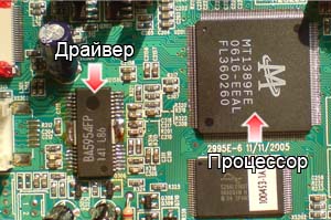 Driver- this is a microcircuit that controls the spindle drive, the positioning motor (the one that rolls the laser head), the focusing coil of the laser lens, the disk loading/unloading motor, in general, all the mechanics.
The driver receives commands from the processor.
Usually, if the driver is faulty, it gets very hot. In this case, malfunctions of mechanical components appear (problems loading/unloading the disc tray, the disc does not spin up, there is no positioning of the laser reader)
It should be noted that during operation the driver heats up (after all, it is an amplifying element), but if the case temperature is clearly too high, then the driver itself is most likely faulty. The same thing happens when an engine malfunctions. The drive consumes too much current, which causes excessive heating of the driver chip.
The most common driver chips are:
BA5954FP (can be labeled as AZ5954M, C5954, CD5954 - all these are analogues), AM5888S
BA5888FP
BA5824FP
BA5814FM
SA9259 (complete analogue of the microcircuit - IP4001).
Replacing a faulty driver quite a troublesome task, since these microcircuits have a planar package, which makes them difficult to dismantle with conventional soldering equipment. To dismantle and install driver chips, it is better to use a hot-air soldering iron (hot air gun) with appropriate attachments.
Typical faults of DVD players and methods for eliminating them
The player does not turn on, the indicator on the front panel does not light up
First, check the serviceability of the power supply and, first of all, the presence of a voltage of 5 V at its output (if this voltage is absent, check the serviceability of the diode D510 and capacitors TC505, TC506, TC510).
If the power supply is completely inoperative, check its input circuits and the PWM converter. First, check the presence of a constant voltage of 310 V on the capacitor TC501, and, in its absence, check the serviceability of fuse F501 and diodes D501-D504. If there is voltage, but it is too low, replace the capacitor TC501. If fuse F501 is faulty, before replacing it, check the diode bridge D501-D504, capacitor TC501 (for leakage) and controller U501 for a short circuit. If the voltage at the pin. 5-8 of the U501 microcircuit is 310 V, but there are no trigger pulses (monitored by an oscilloscope at pins D), check elements D506, TC502, R505, U502. If all of the above elements are in working order, replace the U501 chip.
The player does not switch to operating mode and does not respond to control buttons
Check the voltage of 3.3 V and, if it is not there, elements D509, D513, TC510 (Fig.). If the voltages of 3.3 and 9 V are too low, check the feedback circuit elements U503, C5156 R508, R509 and U502. If there is no voltage at the pin. 3, 4 U501, replace the controller, if it is present, replace the optocoupler U502. It should be noted that if the stabilizer U503 malfunctions, the voltage at the pin. 1 and 2 optocouplers will be the same. If the voltage at the pin. 1 stabilizer U503 is 2.5 V, and the deviation of this voltage exceeds 0.15 V, it is replaced. Using an oscilloscope, check the signal at the pin. 5-8 U301. If the pulse frequency at this pin differs from 100 kHz, the microcircuit is replaced.
If the power supply is working, check the supply voltage of 3.3 V at the pin. 55 chip U201 (Fig), as well as the RESET voltage (3.3 V) on the pin. 188 of the same microcircuit. If the RESET voltage is zero, check the circuit for its formation and the serviceability of the driver U205, transistor Q204 and diode VD201 (Fig.). Then they check for the presence of a 27 MHz clock signal on the pin. 187 and 186 U201. If it is absent, check the generator on elements U205 A/B, X201 and the DVD controller U201 (by replacement). Before replacing quartz, all elements of the quartz oscillator circuit are soldered, special attention is paid to the serviceability of capacitors C222 and C223 (they can be unsoldered for a while, and if the device “starts” at the same time, they are replaced).
Check the operating mode of the EEPROM U202 memory chip, while the voltage on the pin. 8, 5 and 6 should be 3.3 V, and on pin. 1, 2, 3, 4 and 7 are equal to zero. If on pin. 7, connected to pin. 75 U201, there is a voltage of 3.3 V, then you can temporarily disconnect this pin from the bus and connect it to the case. If the device “starts” at the same time, the DVD controller is faulty. If the power supply to the EEPROM chip is normal and no exchange occurs between it and U201 (pins 65 and 67) when the player is turned on, then replace the memory chip. When replacing, there is no need to have firmware for this chip. In place of the faulty memory, a clean one is installed, and when the player is turned on for the first time, the microprocessor in the DVD controller itself “flashes” it. To be completely sure, the hexadecimal code FF is written to all cells of the new memory on the programmer. If all the above measures fail, replace the U201 controller.
Tray won't open
Check the 5 V voltage on pin 4 of connector XS203 of the DSU board. If it is underestimated, then check the capacitors TC505, TC506 and the diode D510 in the power supply (D510 is a Schottky diode (therefore it needs to be replaced with a similar one). If the voltages are too low, 5 and 9 V, check (and, if necessary, replace) the stabilizer U503 (LM431, analogue - TL431), as well as optocoupler U502 (2501, can be replaced with LM817).
If all voltages are normal, proceed to check the DVD drive. Check the serviceability of the loading-unloading mode switching bar, the cleanliness and condition of the gear teeth. They also check the functioning of the limit switch (Fig. 2), for which they push the tray into the manual tray, rotating the tray extension gear, and remove it by bending the locking latches. In the working position, the shift lever must be located between the guides of the shift bar. Check for a short circuit between contacts 3 and 5 with 4 on the XS302 connector (Figure) in the extreme positions of the switch lever.
Check the serviceability of the loading motor. For this purpose, with the motor disconnected from the circuit, a voltage of 5 V is applied to its terminals and the rotation of the axis is controlled. If the axis does not rotate (or rotates with difficulty), you can try to restore the serviceability of the engine by cleaning it from contaminants. To do this, place the motor housing in alcohol and apply voltage to its terminals - in this way they try to rinse it. After washing, the engine is dried with compressed air. If the engine cannot be restored in this way, it is replaced. In this case, you can replace the engine with a similar one from any faulty CD or DVD drive. It is advisable to select a motor with the same winding resistance (about 30 Ohms).
If the engine is working properly, check its control circuits. They control the change in voltage using the OPEN command - at the same time, on the pin. 14 U201 (fig) a high level (3 V) should appear, and when the tray is closed, a high level should appear on the pin. 53 U301 (fig). If these signals are missing, replace the corresponding microcircuit. Then transistors V306, V307, V308, V309 are checked.
Disc loads but can't be read
Monitor the operation of the drive and the OP with the housing cover and the plastic disk holder strip removed. Without installing the disc in the tray, press the OPEN/CLOUSE button, the tray should be in the working position, the OP will move to the beginning, the laser will light up, the focusing and tracking mechanism will turn on and the spindle motor will make several revolutions.
The following cases may occur:
The disk loads and spins, but the laser does not light up
You can determine the serviceability of a DVD laser visually by its bright red glow (650 nm). The serviceability of a CD laser is more difficult to determine, since its radiation (780 nm) is in the invisible part of the spectrum. Its glow can be checked using a digital video or photo camera. In shooting mode, the glow of the CD laser will be visible on the LCD display. If there is no laser glow or it is weak, check the cleanliness and transparency of the lens. A light coating of dust on the lens is allowed. It is not recommended to use a cleaning disc to clean the lens, as its effectiveness is low (dust is not completely removed from the lens). To clean the lens, it is recommended to use glass cleaner (for example, "Mr. Muscle") or a soap solution. Using a cambric cloth soaked in this solution, lightly touching it, wipe the lens in a circular motion from the center to the edge.
If the lens is clean, but there is no laser light, check the voltage of 3.3 V in the power supply. If the voltage differs from the specified one, then repair of the power supply is necessary (see paragraph “The player does not switch to operating mode”). Check the laser supply voltage (3.3 V) on pins 19 and 23 of the XS301 connector, as well as its formation unit on elements V301, V302. The voltage at the collectors of the transistors should be equal to 2.2 V (when the DVD laser is turned on), and 2 V (when the CD laser is turned on). If there are no turn-on voltages LD01, LD02 on the bases of transistors V301, V302, check their circuits from the pin. 125 and 126 U301 chips. If these voltages are absent when loading the disk, then check and replace U301. When the lasers glow weakly, their current can be adjusted using variable resistors installed on the OP board. The adjustment should be made with the player turned off using a thin screwdriver. They also check the quality of the wiring of the protective jumpers (on a new OP they are sealed and are removed directly when installing it in the device). If the above actions do not eliminate the defect, check the serviceability of the laser diodes themselves. This can be done in two ways, after first removing the laser head from the guides.
1st method. An external regulated DC voltage source supplies a voltage of 2 V through a 100 Ohm quenching resistor to the terminals of the corresponding laser diode. If the diode does not light up at a voltage of 3 V, it is most likely faulty. Voltage is applied to the right contact of the laser unit relative to the central point (the output of the monitor diode is on the left), while the “+” of the source is connected to the central contact, and “-” to the right one.
2nd method. A square wave signal with a swing of no more than 1.5 V and a frequency of 1 kHz is supplied to the laser from a rectangular pulse generator. It is strictly forbidden to check the serviceability of laser diodes with analog testers, since their measuring current at low resistances can damage the diodes. Faulty laser diodes are replaced complete with control circuits. You can try replacing the diodes themselves from faulty computer drives. In this case, replacing the CD diode does not cause any difficulties. It is not so easy to replace the DVD diode - it is installed in the control board.
The disk is not readable and rotates intermittently
Check the 5 V voltage at the power supply output. If it is low, see "Tray does not open." When the supply voltage is normal, the power drive microcircuit (motor driver) checks the serviceability of the spindle motor itself in the same way as the loading motor. If the disk rotates intermittently, contamination may occur on the collector (even to the point of rust). It can be cleaned. If you hear extraneous noise from the engine at idle, replace it. Check the supply voltage on pins 5 and 6 of the XS303 connector, which should reach 2 V at maximum engine speed. The lack of rotation of the disk or its intermittent rotation may be due to a malfunction of the laser diodes. In this case, they are checked (see above). They also check the flexible flat cable connecting the optical converter to the main board for mechanical damage, as well as distortions when installed in the connector. A malfunction of the spindle motor (lack of full contact of the brushes with the commutator) can also be determined by the strong heating of the U302 driver.
There is no up and down movement of the lens
Most likely the focusing system is not working. The focusing coil is tested using the FOSO command (pin 1 of the U302 chip), which comes from the DVD controller (pin 12 of the U201 chip). If during testing the voltage between pins. 14 and 13 U302 reaches 4 V, then U201 is OK. If this does not happen, check for the presence of an alternating signal FEO on the pin. 18 U301 chips. If it is absent, while the laser diode is glowing, check the RF signal at the pin. 6 and 7 of the same microcircuit. If the RF signal appears, but the FEO does not, then replace the U302 chip.
Check the serviceability of the focusing coil; its resistance should be about 20 Ohms. Apply a voltage of 2.5...3 V to the focusing coil terminals (the two rightmost contacts on the OP board), and the lens should move. If this does not happen, solder the focusing coil connection contacts. If the focusing coil is faulty, replace the OP. If the lens does not move vertically when the coil and RF amplifier are in good working order, check the voltage at the pin with an oscilloscope. 13 and 14 U302. It should be 4 V and will change within ±0.2 V as the lens moves. If this does not happen, replace U302.
The disk is in the device and cannot be ejected
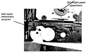
First of all, you need to remove the disc from the tray. To do this, remove the top cover of the player, remove the top plastic fixing bar (by unscrewing two screws) and remove the disc. Without installing the bar in place, check the operation of the loading mechanism by pressing the OPEN/CLOUSE button. If at the same time the tray starts to move, but stops, check the condition of the drive gear and the lifting/lowering bar of the OP (see Fig. 3), for which they remove the tray (bend the plastic fasteners) and check the condition of the teeth. Having replaced the faulty parts, install the tray in place; to do this, turn the loading mechanism gear by hand until the OP takes the lower position. Then insert the tray into the grooves of the drive and push it by hand, bending it slightly until the first tooth of the tray gear line connects with the loading drive gear. The limit switch lever must be located between the outermost projections of the OP lifting bar.
If, when loading the disk again, it does not unload, check the serviceability of the limit switch (see Fig. 2), the receipt of the OPEN signal from the pin. 14 U201 and, if it is missing, check the serviceability of the tray control button on the front panel. If all of the above steps do not produce results, replace the DVDU201 controller.
When loading a disc, the lens moves erratically and may even damage the disc.
The disc loads, but cannot be read, the message "No disc" appears on the TV screen
If there are no problems with the DVD drive (as discussed above), check for the presence of a total RFO signal on pin 8 of the XS301 connector or on each line A, B, C, D (pins 5, 6 and 9, 10 of the XS301 connector). If the laser diode lights up, but there is no signal or it is too small (the signal swing should reach 1.5 V), adjust the current level of the laser diode using adjusting resistors installed on the OP. If the total signal cannot be increased, then the photodetector is faulty. In this case, replace the OP assembly.
If the RFO signal is normal, and the pin. 6 and 7 U301 there are no RFON and RFOP signals, then the problem is related to a malfunction of the high-frequency amplifier. First of all, check for the presence of a voltage of 3.3 V and the URST signal on the pin. 60. If 3.3 V power appears when the XS203 connector is disconnected, check the 3.3 V stabilizer and consumers, sequentially disconnecting the load: AV33 bus (power supply U201), DV33 bus (power supply U301 RF amplifier), faulty elements are replaced. Check the URST signal generation circuit - operational amplifier U205 and capacitor C214. Also check the voltage at the pin. 59 and 56 U301. If it is significantly lower than 3.3 V, check the I2C bus before the pin. 197 and 195 U201. A low voltage level indicates a malfunction of one of the microcircuits. They determine which one is faulty by breaking the I2C bus. If the voltage at the pin. 197 and 195 U201 will increase to 3.3 V, then U301 is faulty. Otherwise - U201.
PLAY mode does not turn on; when loading a disc, the OP moves not to the beginning of the disc, but to the end, or does not move at all
Check the serviceability of the driver U302 (BA5954) and the voltage level at its pin. 8, 9 and 21 (should be 5V). If the voltages are too low and the microcircuit gets very hot, it should be replaced. Analogues of this microcircuit are D5954, AD5954 or AM5954.
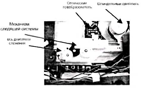
Check the serviceability of the gears and guide pins along which the OP moves (Fig. 4). Check the smooth movement of the OP along the guides. If the OP moves jerkily, wipe the guide axes and lubricate them with special silicone grease. They check the serviceability of the tracking system motor, measure the resistance of its windings with a tester (should be about 20 Ohms). Connect the motor to a 5 V DC voltage source, changing the polarity. In this case, the engine should rotate evenly in both directions. Otherwise, it is replaced. If the engine is faulty, check its control circuit (driver). When moving the motor, the voltage swing across the pin. 17 and 18 U302 must be at least 100 mV (with a supply voltage of 2.5 V). If this voltage is too low, the microcircuit is replaced. If the voltage is zero, check the arrival of the FMSO signal at the pin. 23 U302 from the DVD controller (pin 19). The absence of this signal from the controller may indicate either a malfunction of the controller itself (for example, its overheating) or problems with focusing.
When you turn on the device and load a disc, the indicator starts blinking or turns off completely, messages appear on the TV screen that do not correspond to the actions being performed
If such a defect appears when there is no disk in the tray, check the serviceability of the indicator board of the connecting cable with the main board and the quality of soldering of the indicator itself. This kind of malfunction can be detected by tapping the board (due to the constant mechanical impact on the board, soldering failures often occur.
Incomprehensible behavior of the indicator or lack of information on the TV screen may be due to a faulty Flash memory U214. First of all, check its power supply of 3.3 V (at pin 13-15). If it is absent or low, and there is 3.3 V on resistors R215, R222, R223, then the microcircuit is faulty and needs to be replaced. After replacing the flash memory, it must be flashed (see section "Flash memory chip firmware").
DVDs are not readable
First of all, check the serviceability of the DVD laser diode (see fault above). The signal from the generator must be supplied not directly to the laser diode, but to a capacitor installed at the input of the DVD diode current control board. If the laser diode lights up, but the DVDs are not readable, you can try to adjust the diode current with an adjusting resistor with index “D” (in fact, this resistor regulates the sensitivity of the monitor diode). It is safer to make adjustments with the power turned off. The final control of the laser diode current is carried out by the swing of the RF signal controlled at the pin. 6 and 7 U301 (in DVD playback mode).
If the DVD laser diode lights up during testing, but the discs are not readable, check the presence of the LD01 signal based on transistor V302, as well as the serviceability of the transistor itself. If there is no laser turn-on voltage (2.2 V), then replace the U301 chip.
If the voltage swing level at the pin. 6 and 7 are significantly below 2 V, and the signals on the pin. 97-100 are also underestimated, replacing OP.
CDs can't be read
To test this problem, burn a disc in VCD format. Check the functionality of the CD laser diode (see above). The performance of the CD laser diode can be checked using a digital tester (in this case, an analog device cannot be used). The sensitivity adjustment resistor for the CD monitor diode is installed on the board and is marked with the letter “C”. If, after trying to read a CD, voltage does not appear at the base of transistor V301, check the transistor and microcircuit U301.
The player does not respond to control panel buttons
Check the buttons and the presence of a voltage of 3.3 V on the pin. 61, 62, 63, 64 U201. For a player without a front panel display, this check is sufficient. If the voltages are too low, check and replace the DVD controller (U201). If the device has a display, disconnect connector XS07. When a voltage of 3.3 V appears, check the display controller - the RTS 16311 microcircuit. If the power indicator LED lights up, check the button control matrix on the pin. 10-13. Gating pulses must be present at these pins. If they are absent and the voltage level is low, replace the RT16311 controller.
There is no service information on the display or TV screen, although the player responds to control buttons
For players without a display, check the functionality of the DVD controller. Check the EEPROM U202 memory chip. If the voltage at the pin. 5 and 6 (at a voltage of 3.3 V on pin 8) are too low, then the microcircuit should be replaced or rewritten.
No picture or sound
Check the functionality of the DVD controller. Monitor the presence of signals on the pin. 168 (PTsTS, interlaced scanning), pin. 170 (luminance signal Y, progressive scan) and pin. 181 (SPDATA, digital audio). If they are not there, check the dynamic memory chips U203, U204, as well as the presence of 3.3 V power on the pin. 1, 7, 13, 25, 38 and 44. The serviceability of these microcircuits can be assessed by measuring the voltage at the pin. 2-12 and 39-49 (data exchange buses with the DVD controller). When the buses are in normal condition, a high level is set on them. Since the simultaneous failure of two SDRAM chips is unlikely, if any of them is suspected, it is simply excluded from the circuit (via the power bus). If the player's performance is restored, the disabled chip is replaced.
The lack of picture and sound may be due to a faulty flash memory. For information about its replacement, installation and firmware, see “Flash memory firmware”.
There is no image signal at the VIDEO OUT connector (located on the rear panel of the player), there is sound
Probably, during the last playback, progressive scan was turned on (the signal labeled YPbPr in the menu). This can be verified by monitoring the brightness signal at the rear panel "Y" connector using an oscilloscope. If there is a brightness signal, then progressive scan is enabled. To exit progressive scan mode, proceed as follows. Connect the Y signal output to the TV’s AV VIDEO IN video input. If a distorted splash screen image appears, enter the menu and select a “composite” signal (CVC or PCTS logo) in the video output selection settings. Not all TVs (with the exception of LCD TVs and monitors) allow you to reproduce the YPbPr component signal, since in modern TVs, if the phase of the horizontal pulses fails, the RGB signal outputs are closed. Therefore, according to the second method, connect a cable with coaxial output Y and C to the S-VIDEO connector, connect contact Y to the video input of the TV and enter the menu in the image that appears. If previous attempts do not succeed, reflash the EEPROM U202.
The player turns on, but the indication on the TV screen does not appear immediately
Check for the presence of a voltage of 3.3 V on the pin. 8, 5 and 6 U202. If it is below this value, disconnect the power connector from the DSU board and, if the voltage is restored to a normal level, check the 3.3 V power bus on this board (most often, a voltage drop is caused by a malfunction). If the voltage remains low, check and repair the power supply.
The cause of such a defect may also be a malfunction of the DVD drive or its control. You can determine the defective element by touching the U302 driver with your hand. If the microcircuit gets very hot, check it, as well as the drive motors (especially the spindle motor). Connect to pin. 11 and 12 U302 serviceable motor (you can use a loading motor) or a 6 W incandescent lamp. If the amplifier does not heat up and the motor spins normally, replace the spindle motor. Otherwise, replace U302.
No sound, picture ok
Check for audio signals at the RCA output connectors (L or R). If they are absent, check transistors Q205, Q206 and amplifier U219. The check can be performed as follows: with the TV connected, touch the pin. 2, 6 U219. If there is no AC background in the dynamic heads, check the switches on transistors Q205, Q206 (first of all, control the voltage of -0.5 V at their bases). If it is above zero, check the MUTE1 voltage generation circuit on elements Q218, Q219, VD205, as well as the external microphone connection contacts (must be closed).
Check the power supply of the stereo processor U207 (5 V on pin 14), as well as the presence of a voltage of 3 V on pin. 1 U207. The last voltage comes from op amp U205 after the turntable is turned on. If the voltage is zero, check the DVD controller (pin 158). Low voltage at pin. 158 U201 may be due to either a malfunction of the controller itself or a defect in the Flash memory firmware. Check the receipt of audio data (pulse modulated signal) from the DVD controller via the SDATA bus. If they are not present, then the malfunction is related (as in the previous case) to the controller and flash memory. The same conclusion is made in the absence of synchronization signals SCLK, MCLK. If the input signals are normal, replace U207.
Sound distortion
First you need to find out that the problem is not related to the TV audio channel. Then transistors Q205, Q206, MUTE1 voltage, as well as capacitors C2111 and C2114 are checked for leakage. Monitor the voltages ±9 V and, if one of them is missing, check the power supply.
MIC is not working
They check the microphone itself by connecting it to a known-good device. Check the voltage at the pin. 4 and 8 U601 (should be -9 and +9 V respectively). If the voltage -9 V is much higher than normal, replace the ZD502 zener diode. If, when installing a new zener diode, the voltage decreases significantly, but does not reach -9 V, replace the U601 chip.
If the signal from the microphone is received at the pin. 16 U603, but there is none at the output (pin 15), check the voltage at pin. 2, which should be 2.5 V. If it is very low or equal to zero, replace this microcircuit. Capacitors C614, C622 and C623 are also checked.
Flash memory chip firmware
There are several ways to initially write (firmware) or rewrite a Flash memory chip. On the VVK technical support website, a Flash memory firmware file is posted for each player model. In order to write a new microcircuit, you must first write the firmware file to a blank CD using the NERO program in the data disk creation mode. Then insert the disk with the firmware into the player and load it. Press the PLAY button and download the update program, the message “File is being copied” should appear on the screen. After this, the tray extends automatically, and the update disc is no longer needed. Then the software update is performed automatically. During the firmware process, you cannot press any buttons on the panel or remote control until the tray on the player closes. After this, we can assume that the Flash memory is flashed correctly.
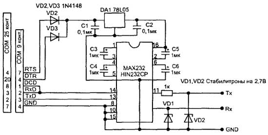
The second method requires a programmer. In this case, you can use the MEDIATEK programmer based on the MAX232 chip (Fig. 5). The main board of the player has a 4-pin service connector XS202 (signals DV33, TXD, RXD, GND), and the programmer is connected to it. You can also make the board yourself (its design differs little from the DATA cables of cell phones). The program for working with this programmer mtktoolv3152_415.exe can be downloaded from the manufacturer’s website. Using this method is only possible if you have a firmware file with the extension .bin or .her. For stable operation of this circuit, it is necessary to use an external power source. The supply voltage can be increased from 3.3 to 5 V, and the firmware speed will increase noticeably.
If there is a need to change the DVD zoning, proceed in the following way. When the player is turned on, enter the “SETUP” menu, sequentially press the number buttons “1-3-5-7” on the control panel (this enters the service mode of the player), then enter the EEPROM 24C02 programming menu. In the additional menu window, select the “Version” item and in the 5th line find the number of the zone used by this player. A player of this type is multi-zone if the “O” zone is in this item.
Installing a new EEPROM memory chip
The new microcircuit must be “clean” or the hexadecimal FF code must be written in the memory cells. After installing the memory chip, the DVD controller itself “registers” its contents the first time it is turned on. If you cannot flash the EEPROM chip in this way, you need to use the firmware by reading the data with the programmer from a working device. Since these devices use a microcircuit in an SMD package, it is more convenient to flash it without removing it from the board. In this case, the SDA and SCL buses and the common wire of the programmer are connected to the corresponding pins of the microcircuit (pins 5, 6 and 7), and the processor reference supply voltage (which is connected to pin 8) is connected to pin. 10 DVD controller MT1379. Turn on the programmer after the DVD logo appears.