1. Classification of cargo
Depending on the type, method of storage and slinging, cargo is classified into the following groups:
- Piece non-stackable loads() – metal structures, engines, machine tools, machines, mechanisms, large reinforced concrete products, etc. The group of piece non-stackable cargo is the most numerous and diverse in shape, therefore there are no uniform standard methods for slinging them, suitable for all cargo in this group.
- Piece stackable loads() - rolled steel, pipes, timber and sawn timber, brick, cinder blocks, standard reinforced concrete products, slabs, panels, blocks, beams, flights of stairs, boxes, barrels and other products of geometrically correct shape.
- Bulk cargo() are transported in containers, grabs, conveyors, etc. They are stored in stacks determined by the angle of repose of the material and bounding surfaces (coal, peat, slag, sand, crushed stone, cement, lime, small metal shavings, etc.).
Figure 1.3 – Bulk cargo
- Semi-liquid plastic loads– loads that have the ability to retain their given shape for some time or harden over time. Such cargoes include concrete masses, mortars, lime paste, bitumen, lubricants, etc. The viscosity of semi-liquid cargo and their hanging on the walls of containers of transport vehicles, the ability to quickly set and harden (concrete, mortar, etc. cargo) make their transportation difficult. Such goods must be transported in special containers.
- Liquid cargo– goods that do not have a specific shape are transported in barrels, cans, bottles, tanks, ladles, etc. (water, liquid flammable and lubricants, acids, alkalis, mastics, etc.).
- Gaseous cargo They are usually transported under pressure in cylinders (), other vessels and pipeline transport.

Figure 1.4 – Container for cylinders
Depending on the weight, cargo is divided into four categories:
- Lightweight cargo– loads weighing no more than 250 kg. These include materials such as felt, leather, tow, plywood, dry plaster, lightweight machine parts, etc.
- Heavy cargo– cargo whose weight ranges from 250 kg to 50 tons. Heavy cargo includes all stackable, bulk, semi-liquid, liquid and non-stackable cargo, the weight of which does not exceed 50 tons.
- Very heavy loads– loads whose weight exceeds 50 tons. These include piece non-stackable loads. Slinging of these loads is permitted only to highly qualified slingers.
- Dead weights– a special category of cargo of unknown mass. Loads that are secured to the foundation with anchor bolts, buried in the ground, frozen to the ground, pressed by another load, or lifted with an oblique beam are considered dead. Lifting dead weights with a crane is prohibited.
Depending on the shape and size, cargo is divided into:
- Dimensional cargo- cargo, the dimensions of which do not exceed the dimensions of the rolling stock of railways, and for automobile and other types of ground-based trackless transport - the norms established by the Road Traffic Rules of the Russian Federation.
- Oversized cargo– cargo whose dimensions exceed the dimensions of the rolling stock of railways or ground trackless transport. Oversized cargo can be large boilers, machines, transformers, etc. The size of the clearance violations should not exceed certain values at which cargo transportation is still possible by reducing the gap between the approach dimensions of buildings and rolling stock.
Depending on the size of the oversize violation, cargo is divided into five degrees of oversize, each of which has its own limiting outlines. When transporting oversized cargo by rail, the corresponding degree of oversized cargo is indicated.
Long cargo constitute a special group of goods (parts and assemblies of large machines, equipment, metal structures, etc.), which are transported on special railway platforms or trailers. Oversized, oversized and long cargo are allowed to be transported in wagons or on platforms only after approval of the loading scheme by the railway department or management.
2. What does the slinger need to know about the load?
To lift a load, its mass, center of gravity and slinging pattern must be known.
The mass of the load can be determined using the formulas:
- for simple loads –Q = m · V ;
- for complex loads –Q = m · ∑ V i,
WhereQ – mass of cargo,m – specific gravity (numerically equal to density) of the material,V – cargo volume,∑V i – the sum of all parts of the cargo volume.
The specific gravity of commonly encountered materials is given in.
Specific gravity of materials
| Materials |
Specific gravity, kg/m 3 |
Materials |
Specific gravity, kg/m 3 |
|---|---|---|---|
|
Sandstone |
|||
|
Wood: |
– hard |
||
|
- birch |
– melt |
||
|
Earth clay |
|||
|
– wet |
How should a slinger act if the mass of the load is unknown?
The slinger is prohibited from slinging loads whose mass is unknown. In this case, the slinger must notify the person responsible for the safe performance of work with cranes and obtain from him information about the weight of the load.
What is the center of gravity of a load? Where it is located?
Load center of gravity- this is the point relative to which the load is balanced in all directions.
The center of gravity of simple-shaped loads (cube, parallelepiped, cylinder, ball) is located in their geometric center. The position of the center of gravity of the load must be indicated by a handling sign if it is shifted relative to the geometric center of the load. In this case, the location for slinging the load can also be indicated with a handling sign ().


Figure 2.1 – Using a manipulation sign
How to perform slinging taking into account the location of the load’s center of gravity?
A load that is strapped without taking into account the location of the center of gravity may end up in an unstable position.
The load will be stable if its center of gravity is located between the slinging points. It is permissible to tie the load with one sling at the location of the center of gravity if the length of the load is no more than 2 m.
What kind of slinging parts can loads have?
Hooking loads with branch slings is a simpler and safer method than tying. For hooking, loads can have loops, eye bolts (), holes, axles (a axle is the bearing or supporting part of an axle or shaft).

Figure 2.2 – Eye bolt
What do manipulation and danger signs indicate?
Handling signs indicate the method of handling the cargo. They are applied to packaging, containers or directly to cargo. Some of the manipulation signs that the slinger needs to know are shown.
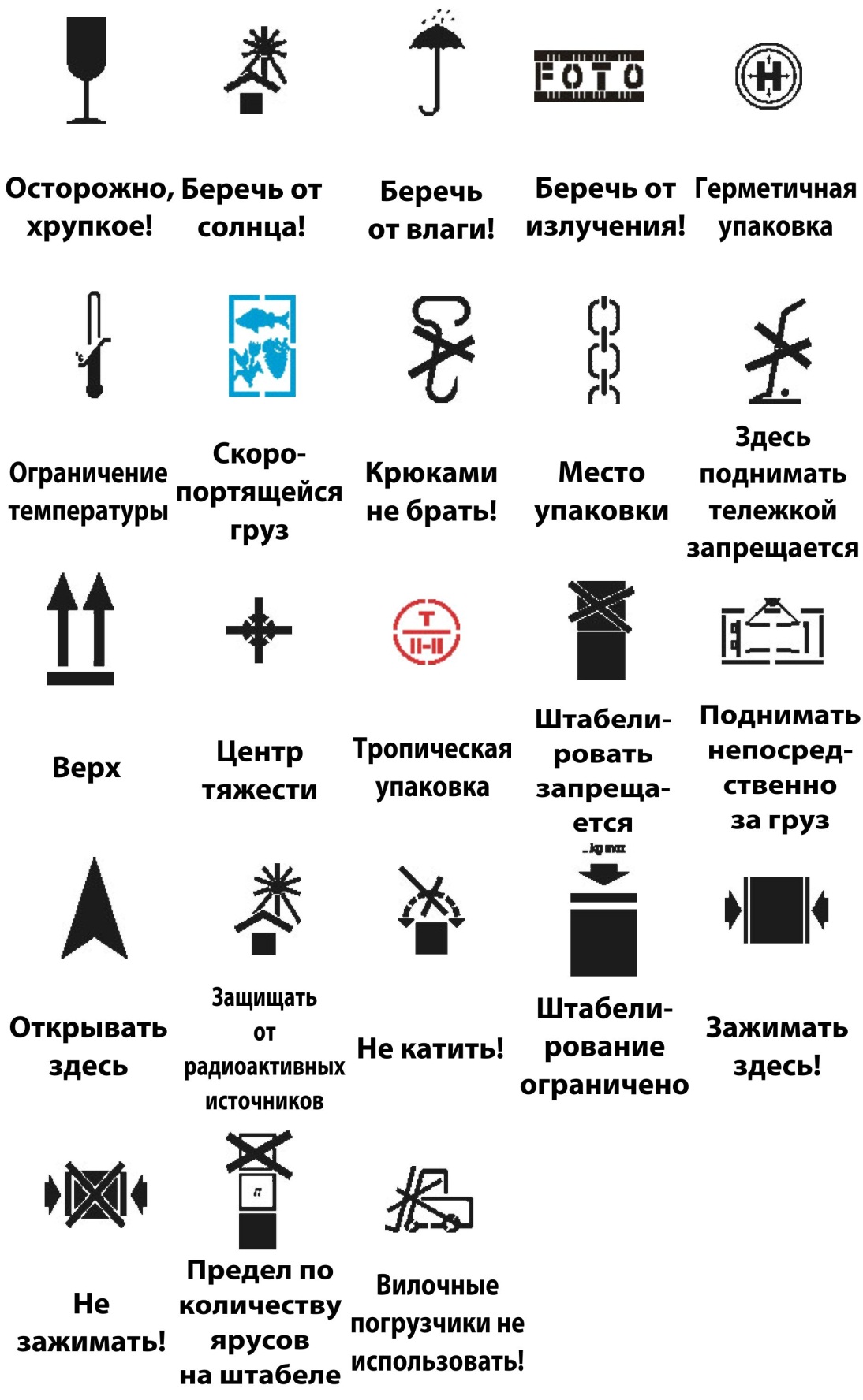
Figure 2.3 – Manipulation signs
Danger signs are applied to goods that, during transportation and loading and unloading operations, can cause harm to people and the environment. The danger sign is a square mounted on an edge, in which a symbol is depicted indicating the type of danger (explosion hazard, fire hazard, toxicity, radioactivity, etc.).
Before performing loading and unloading operations with dangerous goods, the slinger must be instructed.
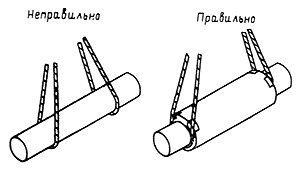
Figure 2.6 – Transportation of cargo with loose stowage on loop slings
10. When tying loads with chain slings, do not allow the links to bend on the edges of the load ().

Figure 2.7 – Slinging loads with chain slings
11. Moving cargo using hook slings is shown in.

Figure 2.8 – Installation of the sling hook in the eye
12. Slinging loads from stacks (rolled metal, pipes, timber, etc.) should be carried out in the following sequence:
- on the most protruding end of the structure, located in the top row, a loop of a ring sling is put on, hanging on the hook of a two- or four-branch sling;
- the slinger moves to a safe distance and gives the command to raise the end of the load to a height of 0.4-0.5 m;
- the slinger approaches the raised load from the side and places wooden pads with a cross-section of 100×100 mm under it at a distance of ¼ from its ends (when lifting pipes and logs, there should be stops on the pad to prevent the load from rolling out);
- the slinger moves to a safe distance and gives the command to lower the load onto the pads and loosen the sling (safe distance means the distance to places that are outside the danger zone at the appropriate lifting height; these places should not be in the danger zone);
- The slinger approaches the load and, using a metal hook (made of wire with a diameter of 6 mm), places the ring slings under the load at a distance of ¼ of the length of the load from its end, then removes the first sling, and tightens the supplied ring slings onto a “noose” and puts two hooks on them. or four-legged sling;
- The slinger gives the command to lift the load to a height of 20-30 cm, makes sure that the sling is secure and gives the command to further move the load.
13. Slinging a load into a girth (on a “noose”) with a load length of less than 2 m is allowed to be done in one place (except for rolled metal).
14. Unslinging of structures installed in the design position should be done only after they have been permanently or reliably temporarily secured.
15. The movement of small-piece cargo must be carried out in containers specially designed for this purpose. In this case, the possibility of individual loads falling out should be excluded. To avoid spontaneous loss of cargo, containers must be loaded 100 mm below its sides.
16. To install structures at height, it is necessary to use load-handling devices with remote slinging.
4. Selection of lifting devices
When moving a load, load-handling device or container horizontally, it should first be lifted 500 mm above equipment, building structures and other objects encountered along the way.


Table of masses of loads supplied to the remote platform
XIII. Warehousing of materials, structures, products and
equipment
13.1. The surface of the site for storing materials, structures, products and equipment must be planned and compacted. In case of weak soils, the surface of the site can be compacted with crushed stone or laid with road slabs on a sandy base.
Storage of materials is carried out outside the soil collapse prism of unsecured excavations, and their placement within the soil collapse prism of excavations with fastening is allowed subject to a preliminary check of the stability of the fixed slope according to the fastening passport or by calculation taking into account the dynamic load.
Loads (except for ballast unloaded for track work) with a stack height of up to 1.2 m must be located at a distance of at least 2.0 m from the outer edge of the head of the crane track closest to the load, and at a higher height - at least 2.5 m according to the requirements of GOST 12.3.009-76*.
To drain surface water, a slope of 1 - 2° should be made towards the outer contour of the warehouse with the installation of ditches if necessary.
13.2. Slingers must know the storage locations for materials provided for in the PPRk.

Regulatory documentation database: www.complexdoc.ru
13.3. Places for storing materials and structures, as well as places for installing warehouse equipment, are marked on the construction site according to the example in Figure 34.
1 - bricks on pallets; 2 - spacer floor slabs - h up to 2.5 m; 3 -
spanning floor slabs - h up to 2.5 m; 4 - outer spacer plates - h up to 2.5 m; 5 - shear walls - h up to 2.5 m; 6 - crossbars - h up to 2 m; 7 - flights of stairs - h up to 2 m; 8 - wall panels in a pyramid - h up to 2 m; 9 - stained glass windows in the pyramid; 10 - partitions in the pyramid with shelter from precipitation; 11 - columns - h up to 2 m; 12 - platform for edging structures.
Rice. 34. Approximate plan for the placement of goods at an on-site warehouse
Notes
1. Storage is carried out in such a way that the weight of the structures corresponds to the lifting capacity of the crane.
2. Temporary roads are arranged in such a way as to ensure the acceptance of all cargo within the crane's lifting capacity.
3. The R/Q scale (may not be shown in the PPRk) will facilitate the placement of loads within the load characteristics of the crane.
4. At the storage site, signs are installed with the name of the cargo and their quantity in the stacks.
13.4. Materials, structures, products and equipment should be placed in accordance with the requirements of the standards,
Regulatory documentation database: www.complexdoc.ru
interindustry rules on labor protection during loading and unloading operations and placement of cargo, SNiP 12-03-2001 or technical specifications of manufacturers.
13.5. In the absence of standards and technical specifications from manufacturers, the following methods of storing the main types of materials and structures are recommended:
- bricks in bags on pallets - no more than two tiers; in containers - in one tier, without containers - no more than 1.7 m high. Bricks should be stored according to grades, and facing ones - according to colors and shades. In autumn and winter, it is recommended to cover stacks of bricks with sheets of roofing felt or roofing felt;
- wall panels - in pyramids or special cassettes in accordance with the passport for the specified equipment, taking into account the geometric dimensions of the products and their stability during storage;
- partition panels - vertically into special cassettes in accordance with the passport for the cassette. Gypsum concrete panels are allowed to be installed in a pyramid with a deviation from the vertical by an angle of no more than 10°. Gypsum concrete partitions must be protected from precipitation;
- wall blocks - in a stack in two tiers on linings and with gaskets;
- floor slabs - in a stack no more than 2.5 m high on pads and with gaskets, which are placed perpendicular to the voids or the working span;
- crossbars and columns - in a stack up to 2 m high on pads and with gaskets;
- foundation blocks and basement wall blocks - in a stack no more than 2.6 m high on pads and with gaskets;
- shear walls, depending on the type of transportation from the factory - in pyramids or similar to floor slabs;
- round timber - in a stack no more than 1.5 m high with spacers between the rows and installation of stops against rolling out; a stack width less than its height is not allowed;
Regulatory documentation database: www.complexdoc.ru
- lumber - in a stack, the height of which when stacked in rows is no more than half the width of the stack, and when stacked in cages - no more than the width of the stack. In any case, the height of the stack should not exceed 3 m;
- small-grade metal - in a rack no more than 1.5 m high;
- sanitary and ventilation units - in a stack no more than 2.0 m high on pads and with gaskets;
- large and heavy equipment and its parts -
V one tier lined;
- glass in boxes and rolled materials - vertically in one row on linings;
- bitumen - in a special container to prevent its spreading;
- ferrous rolled metals (sheet steel, channels, I-beams, section steel) - in a stack up to 1.5 m high on pads and with gaskets;
- thermal insulation materials - in a stack up to 1.2 m high, stored in a closed, dry room;
- pipes with a diameter of up to 300 mm - in a stack up to 3 m high on pads and with gaskets with end stops;
- pipes with a diameter of more than 300 mm - in a stack up to 3 m high in a saddle without gaskets with end stops.
The bottom row of pipes must be laid on supports, reinforced with inventory metal shoes or end stops securely fastened to the support.
When storing reinforced concrete elements with hinges (slabs, blocks, beams, etc.), the height of the spacers must be at least 20 mm greater than the protruding part of the mounting hinges.
Storage of other materials, structures and products should be carried out in accordance with the requirements of standards and technical specifications for them.
Regulatory documentation database: www.complexdoc.ru
13.6. Between stacks (racks) there must be passages with a width of at least 1 m and passages, the width of which depends on the dimensions of vehicles and cranes serving the warehouse.
13.7. When storing cargo, factory markings must be visible from the aisles.
13.8. It is advisable to place panels of the same brands in the pyramids. The panels must fit tightly to each other over the entire plane. One-sided loading of pyramids is not allowed.
It is necessary to install products in cassettes, pyramids and other equipment of an on-site warehouse in such a way that during storage, both the products themselves and the warehouse equipment cannot lose stability. Products are installed taking into account their geometric dimensions and shapes.
13.9. Between stacks of structures of the same name stacked side by side (floor slabs), or between structures in a stack (beams, columns), there must be a distance of at least 200 mm.
13.10. The height of a stack or a number of stacks on a common laying should not exceed one and a half of its width.
13.11. In stacks, the gaskets are arranged along one vertical line. The location of the gaskets depends on the operating conditions of the product in the structure.
13.12. Each stack must contain structures and products of one-dimensional length.
13.13. When arranging materials and structures, it is necessary to take into account the requirements PPB 01-03.
Storage of materials and structures above underground utilities or in a security zone is permitted only with the written permission of their owner.
13.14. When conditions change or in case of production necessity, the person responsible for the safe performance of work with cranes can make additions and changes to the storage scheme for materials and structures provided for in the PPR, in compliance with the requirements of standards, technical specifications of manufacturers and other regulatory and technical regulations.
Ensuring safety when using lifts
Occupational safety at urban construction and economic sites when using cranes and lifts.
Educational, methodological, practical and reference manual.
Authors: Roitman V.M., Umnyakova N.P., Chernysheva O.I.
Moscow 2005
1. OCCUPATIONAL HAZARDS WHEN USING CRANES AND LIFTS.
1.1. Concept of industrial hazard.
1.2. Danger zones on a construction site.
1.3. Examples of typical accidents and accidents associated with the use of cranes and hoists.
1.4. The main causes of accidents and accidents when using cranes and hoists.
2. GENERAL ISSUES OF ENSURING LABOR SAFETY WHEN USING CRANES AND LIFTS.
2.1. General condition for ensuring occupational safety.
2.2. Regulatory framework for ensuring occupational safety when using cranes and lifts.
2.3. The main tasks of ensuring occupational safety when using cranes and lifts.
3. ENSURING LABOR SAFETY WHEN USING CRANES AND LIFTS.
3.1. Selection of cranes and their safe binding.
3.1.1. Crane selection.
3.1.2. Transverse connection of cranes.
3.1.3. Longitudinal tie-down of tower cranes.
3.2. Determination of the boundaries of hazardous areas for the operation of cranes and lifts.
3.3. Ensuring labor safety in hazardous areas of cranes and lifts.
3.3.1. Instruments and safety devices installed on cranes.
3.3.2. Ensuring safety when installing cranes.
3.3.3. Protective grounding of crane tracks.
3.3.4. Ensuring safety during joint operation of cranes.
3.4. Measures to limit the hazardous area of crane operation.
3.4.1. General provisions.
3.4.2. Forced limitation of the crane operating area.
3.4.3. Special measures to limit the hazardous area of crane operation.
3.5. Ensuring occupational safety when installing cranes near power lines.
3.6. Ensuring occupational safety when installing cranes near excavations.
3.7. Ensuring safety when storing materials, structures, products and equipment.
3.8. Ensuring safety during loading and unloading operations.
4. SOLUTIONS TO ENSURE LABOR SAFETY IN ORGANIZATIONAL AND TECHNOLOGICAL DOCUMENTATION (PPR, POS, etc.) WHEN USING CRANES AND HOISTS.
4.1.General provisions.
4.2. Stroygenplan.
4.3. Technological diagrams.
3.3.5. Ensuring safety when using lifts.
To lift workers to workplaces during the construction of buildings and structures with a height of 25 m or more, it is necessary to use cargo-passenger lifts.
The lifting capacity of the lift is determined by its passport.
Installation and operation of lifts should be carried out in accordance with the requirements of the installation and operation instructions of manufacturers or specialized organizations, relevant standards, guidelines, recommendations.
Before installing the lift, plan the site and concrete the slab with the installation of anchor bolts along the conductor or support frame.
The lift is attached to the building according to an individual project. The lift must be grounded.
Climbing to the roof should be done after dismantling the tower cranes. During operation of the cranes, the head of the lift must be at least 0.5 m below the installation horizon.
An alarm system must be connected to the lift control area from all floors.
It is prohibited for people to be in the danger zone caused by the lift (Fig. 3.5, 3.6).
During non-working hours, the lift cabin should be in the down position.
On the floors opposite the elevator car stop, it is necessary to install doors at the opening height (h=1.8m) and 1.2m wide. Doors must have special locks that can be locked from the outside of the building. On the floors and roof, for unloading materials and exiting people from the lift, it is necessary to arrange a platform the width of the opening and 1 m long with a ramp, the angle of inclination should be no more than 300. The platform and the ramp must have a railing.
A protective canopy 1.0 x 1.5 m made of 40 mm thick boards is installed over the motor operator’s workplace, located outside the danger zone.
Two-way visual communication (or an alarm system) must be established between the motor operator and the worker accepting the goods.
A stand must be installed at the lift at the loading point, which shows the lift’s lifting capacity, a table of cargo masses with a list and quantity of cargo and packaging methods, a list of responsible persons and rules for using the lift.
Place warning signs along the danger zone. It is prohibited for people to be in the danger zone of the lift during the lifting period. It is also prohibited to work on a faulty lift or go onto the loading area.
The site where the lift is installed must be horizontal, the foundation cavities must be filled and compacted in accordance with the requirements of building codes and regulations to the density of the soil according to the project. A monolithic reinforced concrete slab or prefabricated reinforced concrete road slabs, or a special slab in accordance with the requirements of the manufacturer’s installation and operating instructions must be installed under the lift’s supporting frame. In Fig. Figure 3.17 shows an example of the design of a monolithic reinforced concrete slab for the installation of a cargo-passenger elevator MGP-1000V.
The construction hoist is attached to the building frame structures after all components of the building frame have been completed in accordance with the working design.
The lift is attached to the building according to the design developed for the given building, subject to:
– the strength of monolithic structures of the building frame and its components at the start of operation of the lift must be at least 70% of the design strength; the possibility of operating the lift with lower concrete strength of monolithic structures of the building and its components is agreed upon with the design organization - the author of the building design;
– the possibility of attaching the lift to the building structures and the attachment points must be agreed upon with the design organization developing the project for this building (or developing the project for its reconstruction). If necessary, the design institute develops a project to ensure the stability of the building from the effects of loads created by the lift.
At the entrance to the passenger-and-freight elevator cabin, at the first stop (on the surface of the ground), a ramp and a protective canopy are installed, similar to the canopy of the entrance to the building.
The openings at which the passenger-and-freight elevator cabin or the freight elevator platform stops must be closed with doors with special shutters installed for the passenger elevator on the outside of the door, and for the freight elevator on the inside.
The doors in the openings of the building are opened (closed) by the driver for a passenger-and-freight lift, and by the workers responsible for accepting cargo on the floors when using a freight lift. The doors of the openings, regardless of the type of lift and installation conditions, must always open into the room.
When constructing buildings with balconies (loggias), lifts must be installed near these balconies in order to use balcony doors to enter the building. At the same time, it is prohibited to store cargo on the platforms of balconies (loggias).
When installing the lift near a balcony or loggia, you need to use a balcony door, installing a latch or latch on it from the outside. The passage from the lift to the balcony door should be fenced on both sides with a fence 1.2 m high from the platform floor level to the lowest point of the upper horizontal element in accordance with GOST 12.4.059-89.
Doors with a height of 1800 mm and a width of at least 1200 mm must be installed opposite the stop of the passenger-and-freight elevator cabin so that the retractable platform or elevator ladder can enter the inside of the opening.
If the height of the opening is less than 1800 mm, it is necessary to ensure a safe entrance to the opening (arrange inclined canopies on both sides of the opening; the canopy on the side of the cabin does not reach it by 350 mm; cover the canopies and the top of the opening with soft material, install warning signs, paint the canopies in signal colors, install additional instruction).
Wall of an existing building
Fig.3.17. An example of the construction of a monolithic reinforced concrete slab for the installation of a cargo-passenger lift MGP-1000V
Loading and unloading operations with an opening height of less than 1400 mm are prohibited.
If a lift is installed near a building that does not have floor-to-floor enclosing structures (including a parapet on the roof), a continuous fence along the floor to a height of 1.6 m is installed on both sides of the installed doors along the facade of the building at least 2 m in each direction, meeting the requirements of GOST 12.4.059-89.
To allow people to exit the lift cabin and unload materials into window openings, at the level of the lower part of the window opening, a receiving platform is arranged the width of the opening and at least 1 m long with a ramp, the angle of which should not be more than 300 (Fig. 3.18).
The reception area and ramp are made in accordance with the design of a specialized organization. Similarly, they arrange a platform with a ramp through the parapet at the exit to the roof. It is prohibited to go out onto the loading platform of a construction lift.
The control area of the passenger-and-freight elevator must be connected to an alarm system from all floors, or the elevator must be equipped with telephone or radio communication with each floor (with each receiving platform). The communication line must be independent of the lift's power supply.
In the building, numbers corresponding to the floor numbers must be marked next to the openings on the outer and inner sides of the walls or fences.
The control apparatus of a cargo lift must be installed in a place with sufficient visibility of the loading and unloading areas and outside the danger zone from the building under construction and the lift. Installation locations are determined in the PPR. During non-working hours, the switch and power supply cabinet of the lift must be de-energized and locked.
It is not allowed to load the lift with a concentrated load whose weight exceeds 200 kg.
To supervise the safe operation of lifts, the owner of the lift must appoint a specialist to supervise the safe operation of the lift.
The owner must assign responsibility for maintaining the lifts in good condition to a specialist who is subordinate to the personnel servicing the lift.
In each workshop, on a construction site or other area of work of lifts, in each shift, a person responsible for the safe performance of work by lifts must be appointed from among foremen, foremen, site managers, as well as foremen, certified in accordance with Section 10 of the Rules for the Construction and Construction of Lifts. safe operation of elevators”, approved on January 26, 1971.
To operate the lifts, the following must be appointed: by order of the construction and installation organization, persons responsible for the operation of electrical equipment on the construction site, persons involved in accepting cargo on the floors, a freight lift operator, as well as slingers for a lift with a cantilever boom, by order of the organization of the owner of the cargo-passenger lift operators.

Rice. 3.18. Linking of remote platforms for receiving cargo.
A– protruding part of the platform; V– width of the platform; With– width of the main flooring; d, d1– site reference dimensions;l– the size between platforms is at least 1 m.
Persons who have undergone training and have the appropriate certificate for the right to operate this type of lift are allowed to operate the lift.
It is prohibited to transfer control of the lift to others or to work on a faulty lift.
For all loads lifted by the lift, a table of load weights is drawn up, which is handed to the conductor-driver, the workers performing the loading, and posted at the loading and unloading points of the lift. The table indicates the weight of a unit of cargo, packaging methods, the maximum number of cargoes and their total maximum weight allowed for lifting or lowering (Table 3.2)
Table 3.2.
Form of a table of masses of loads supplied to the remote platform.
When determining the maximum mass of cargo moved by a passenger-and-freight lift, it is necessary to take into account that there must be a driver-conductor in the cabin, therefore the value of the maximum mass of cargo must be 100 kg less than the lifting capacity of the lift. The form of the table of masses of loads moved using a lift is given in Table 3.3.
Table 3.3.
Form of a table of masses of loads moved using a lift.
| No. | Name of goods | Brand, size | Unit change | Packing method | Col. units per lift, pcs. | Weight of a unit of cargo, kg | Total weight per lift, kg |
| 1 | Solution | M-50 | PC. | Stretcher | 5 | 60 | 300 |
| 2 | Ruberoid | RB | PC. | Roll | 10 | 40 | 400 |
| 3 | Mastic | B-1U | PC. | Flask | 6 | 60 | 360 |
| 4 | Metlakh tiles | 150x150 | PC. | Box | 20 | 20 | 400 |
| 5 | Brick | M-75 | PC. | T-200 trolley | 1 | 200 | 200 |
For cargo lifts with a cantilever boom, load slinging schemes with a table of load weights and used load-handling devices should be developed as part of the PPR.
The boundary of the danger zone for lifts is determined in accordance with Section 3.2 and Fig. 3.5 and 3.6.
The signal fence placed along the contour of the dangerous zone of lifts must meet the requirements of GOST 23407-78.
Access roads, cargo storage areas and a canopy (size 1.0 1.5 m) for the mechanic (for a cargo lift) must be located outside the danger zone.
The proximity of the lift, its cabin or the cargo lift platform to the building or its protruding parts is determined by the operational documentation of the manufacturing plants.
The joint work of a construction hoist with load-lifting cranes is carried out in accordance with the table of joint safe work, while
The installation console of the lift must always be at least 0.5 m below the installation horizon.
Moving a crane boom with a load on a hook over a lift is only possible when the lift is not working.
During the period of crane operation in the lift area, the latter must be turned off, and the keys to the power supply cabinet, switch, cabin doors, and lower railing of the lift must be kept by the lift operator. The operation of the lift stops if the distance from the dangerous zone of the crane to the lift is less than 2 m; the dangerous zone is determined by the height of movement above the exit level from the cabin.
To ensure joint safe operation of cranes and hoists, it is planned to install a single switch for cranes and hoists - in one position of the switch only the crane works, in another - only the hoist, in the third - the line is de-energized and the mechanisms do not work. Installation of the switch in the appropriate position is carried out by the person responsible for the safe operation of cranes.
When a crane and a hoist are working together on the installation level, a light alarm can be installed at the hoist, which turns on when the power supply to the hoist is turned on, and while it is lit, the crane operator should not bring a load to the hoist to the extent of the danger zone provided for in the PPR. As the building is erected, the alarm system is moved from one installation level to another. The light signaling must be clearly visible from the crane cabin.
On the joint operation of a cargo-passenger hoist and a tower crane in accordance with their work schedule, special instructions are given to the driver-conductor and the crane operator and recorded in the logs of these machines.
The basic rules for using the lift must be posted on the platforms from which the cabin is loaded or unloaded.
The rules for using the lift must contain the loading method, the signaling method, the procedure for servicing the doors by workers on duty, the prohibition of people entering the platform of cargo construction lifts, the prohibition of loading the cabin with flammable and explosive goods and toxic liquids in glass containers without special packaging and other instructions for servicing the lifts.
Can the breaking force in the sling branches exceed the weight of the load lifted with their help? Ask this naive question to slingers, crane operators, foremen... It is unlikely that the majority will answer correctly, although their understanding of this issue is the key to safe work!..
Misunderstanding can really threaten the health, and even the life, of both the slinger himself and the people around him.
In this little article I will show on an Excel chart, how when the angle between two slings increases, the breaking force acting in them increases like an avalanche. All this is elementary simple and at first glance does not deserve special attention, but due to the significant importance of understanding this issue, I decided to briefly touch on the topic of calculating slings with branches operating at an angle to the vertical. For everyone involved in loading and unloading operations, this is another and, I think, useful reminder of the importance of knowing and following the rules for slinging cargo!
Calculation of forces in sling branches in Excel.
The slinging diagram that will be discussed is shown in the figure located just below this text.

Conditions of the problem:
Load weighing G with the center of gravity at point C, is hooked to points A and B by a two-leg sling. The upper ring of the sling is put on the crane hook (not shown in the figure). Angle between sling branches – α . It is required to find the forces in the branches of the sling T at different angles α .
Download MS Excel or OOo Calc and start calculating the slings!
General formatting rules that apply to all Excel files presented on the site can be found on the page " ».
Initial data:
1. Angle between sling branches α enter in degrees
to cell C15: 30
Calculation of forces in sling branches:
2. The force arising in each of the branches of the sling T expressed as a percentage of the weight of the load being lifted G we count
in cell C16: =½/COS (C15/2*PI()/180) =52%
T = 1/(2* cos(α /2))

The graph clearly shows the rapid nonlinear increase in force in the branches of the sling (which we talked about at the very beginning of the article) with an increase in angle of more than 120 degrees! If at angle α equal to 90 degrees, each branch of the sling is loaded with force T equal to 71% of the cargo weight G, then at the angle α equal to 120 degrees force in each of the branches T already equal to the weight of the load G, and at angle α equal to 150 degrees force in each of the branches T will reach almost double the weight of the load G!
When choosing a sling, you should know the weight of the load and understand the location of the center of gravity in order to correctly determine the hook points.
It is important to choose the correct length of the sling branches! That's right - this is when the angle between the lines is in the range from 60 to 90 degrees. At this angle, the load is most stable from arbitrary turns and overturns. In this case, as a rule, the lifting height is not lost too much.
Based on the above, it is recommended that the slinger (both crane operator and foreman) ensure that the angle between the slings does not exceed 90 degrees (or 45 degrees to the vertical)! Of course, the sling must be selected with branches of the appropriate load capacity and the required length.
Most often, violations of the above rule occur when there is a small selection of slings or when the lifting height is insufficient. Then you have to sling the load with an angle between the branches greater than 90 degrees, and sometimes greater than 120 degrees. In this case, you need to be three times careful and double-check the strength of the sling branches with calculations, despite the fact that they are manufactured with a significant safety factor (5 for chain slings, 6 for rope slings, 7 for textile slings)!
Those responsible for the safe performance of work, do not forget to inspect the slings every 10 days and make appropriate entries in the load-handling equipment registration log! The sling must be tested every six months of operation.
To receive information about the release of new articles please subscribe for announcements in the window located at the end of the article or in the window at the top of the page.
After entering your email address and clicking on the “Receive article announcements” button don't forget to confirm your subscription by clicking on the link in a letter , which will immediately come to your email address. !
I beg respecting the author's work download file after subscription for article announcements!
I will be glad to see your comments, dear readers!!!
16.21. For cargo lifts with a cantilever boom, load slinging schemes with a table of load weights and used load-handling devices should be developed as part of the PPR.
16.22. Lifts in operation are equipped with plates indicating the registration number, load capacity, date of the next technical inspection, owner’s name and telephone number.
16.23. The joint work of a construction hoist with load-lifting cranes is carried out in accordance with the table of joint safe work, while the mast (shaft) of the hoist must always be at least 0.5 m below the installation horizon.
Moving a crane boom with a load on a hook over a lift is only possible when the lift is not working.
During the period of crane operation in the lift area, the latter must be turned off, and the keys to the power supply cabinet, switch, cabin doors, and lower railing of the lift must be kept by the lift operator. The operation of the lift stops if the distance from the dangerous zone of the crane to the lift is less than 2 m; the dangerous zone is determined by the height of movement above the exit level from the cabin.
To ensure joint safe operation of cranes and lifts, it is planned to install a single switch for cranes and lifts - in one switch position only the crane works, in another - only the lift, in the third - the line is de-energized and the mechanisms do not work. Installation of the switch in the appropriate position is carried out by the person responsible for the safe operation of cranes. When a crane and a hoist are working together on the installation level, a light alarm can be installed at the hoist, which turns on when the power supply to the hoist is turned on, and while it is lit, the crane operator should not bring a load to the hoist to the extent of the danger zone provided for in the PPR. As the building is erected, the alarm system is moved from one installation level to another. The light signaling must be clearly visible from the crane cabin.
The combined operation of a freight or cargo-passenger lift with a façade lift (cradles, platforms) is not permitted if the façade lift is located within the dangerous zone of operation of other lifts.
16.24. On the joint operation of a cargo-passenger hoist and a tower crane in accordance with their work schedule, special instructions are given to the driver-conductor and the crane operator and recorded in the logs of these machines.
16.25. The basic rules for using the lift are posted on the landing (loading) areas.
They contain instructions on the procedure and methods of loading, the procedure for exchanging signals between the driver and workers, opening and servicing doors, prohibiting or allowing people to enter the loading platform, as well as other instructions and requirements. At all loading or unloading points of the lift, inscriptions are made indicating the mass of the maximum load allowed for lifting or lowering.
16.26. The presence of people under the lifted load-carrying device is prohibited for the entire period of operation of the lift.
Before lifting a platform with a load, the operator is obliged to warn the workers servicing the lift about the need to leave the danger zone and not to lift the platform as long as they are in the danger zone.
16.27. When lifting a load, you must first raise the loading platform to a height of no more than 200 mm, make sure the brakes are working properly and the mast is stable, and only then continue lifting to the required height.
Lifting and lowering people, as well as flammable and explosive goods on the loading platform is not permitted.
16.28. Operation of the lift at wind speeds exceeding the permissible level, at temperatures below those specified in the passport, during snowfall, rain or fog, as well as in the dark or in the absence of the necessary lighting, is prohibited.
16.29. Before starting work, the lift operator inspects and checks the lift, makes sure that the danger zone fences are in good working order, and that there are warning signs and safety signs.
16.30. The lift connection diagram in the work project shows:
The current situation with existing and designed underground, above-ground and air communications and the site of the building (structure) being erected, its axes, marks of openings and ceilings;
Lifts with a cabin (platform) in the upper and lower positions with horizontal and vertical binding;
Base plate or foundation with horizontal and vertical reference;
Dangerous zones (from the lift and the building) and signal fencing along them;
Warehousing of materials and other cargo;
Ramp and canopy at the entrance to the passenger-and-freight elevator cabin;
Platforms and ramps on floors and roof;
Canopy for the operator of a cargo lift;
Fencing the edges of floors and coverings in the absence of enclosing structures (along the facade of the building);
Closable openings;
Temporary roads (access to the ski lift) and pedestrian paths;
Mounting lifts.
16.31. Facade lifts (cradles) are suspended from consoles installed on the roof of the building (structure).
The design of the consoles of facade lifts (cradles) should provide for their disassembly into separate units, allowing them to be moved manually.
16.32. A single-suspension cradle is suspended on one lifting rope and must have one safety rope, a double-suspension cradle must have two lifting ropes and two safety ropes.
Load-bearing steel ropes used for suspending and lifting facade lifts (cradles) must meet current state standards and have a manufacturer’s certificate of testing.
The movement of ropes when raising and lowering facade lifts (cradles) must be free. Friction of ropes against protruding structures is not allowed.
16.33. Freely installed lifting winches of façade lifts (cradles) are loaded with ballast. The minimum mass of ballast must correspond to twice the calculated traction force of the winch.
16.34. When installing facade lifts (cradles), the distance from their protruding parts (not counting the support rollers on which the cradle can rest during lifting) to the protruding parts of the building must be at least 200 mm.
It is prohibited to set the extension of the consoles from the outer plane of the building wall to the axis of the load rope of the façade lift (cradle) in excess of 550 mm. The fastening of the ropes to the consoles must be checked systematically, after each movement of the cradle to a new grip. Pads or supports for consoles should be connected to the console with a chain or rope to prevent them from accidentally falling to the ground. Safety and cargo ropes must be reliably tensioned by weights located at a height of at least 200 mm from the ground. Safety ropes are not subject to lubrication.
16.35. The joint operation of two or more façade lifts (cradles) in one vertical grip is prohibited. The horizontal distance between electric façade lifts (cradles) when operating on vertical arms must be at least 3.5 m.
It is prohibited to connect two facade lifts (cradles) to each other by installing transitional flooring and stepladders or installing transitional stairs.
16.36. In places where the façade lift (cradle) operates, stands are installed with a list and weight of the goods being moved.
When working from façade lifts (cradles), door and window openings are tightly closed with wooden panels or with closing devices for frame sashes. Lifts (cradles) from which work is not performed must be lowered to the ground.
16.37. When operating a façade lift (cradle), in accordance with the requirements of clause 4.5.12 PB 10-518-02, the following procedure must be observed:
Entry into and exit from the cradle must be carried out when the cradle is in the lowest position;
Working cradles must undergo a medical examination in accordance with the established procedure for the right to work at height;
Cradle workers must work in helmets and with a safety belt fastened to the structural elements of the cradle;
Cradle workers are prohibited from sitting or standing on the railing, or placing objects on the cradle floor to increase the height of the work area;
The weight of workers with tools (load) should not exceed the established rated carrying capacity of the cradle.


